63
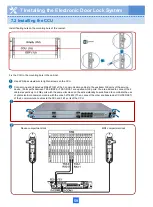
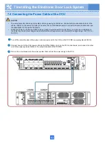
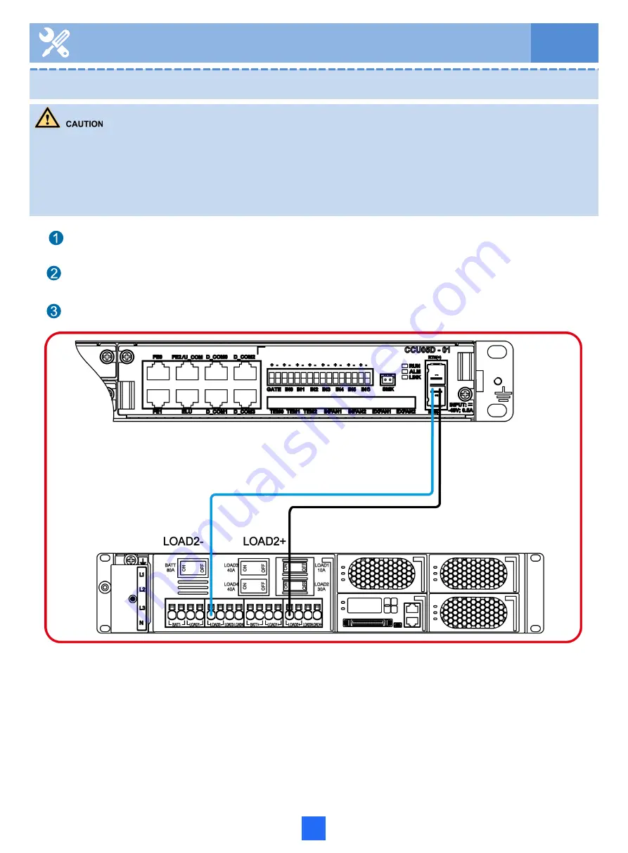
Connect one end of the CCU power cable to the RTN(+)\NEG(-) port on the CCU control board, and connect the other
end to the power system(LOAD2) or the output terminals of the DC PDB.
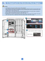
• To ensure personnel and equipment safety, before powering on the device, check whether condensation exists in the
cabinet. Power on the device only after you ensure that no condensation exists. For how to remove condensation, see
the related label on the cabinet front door.
• During the power-on, before and after turning on each circuit breaker for the first time, you must use a multimeter to
check the input and output voltages and ensure that the voltages are normal (normal DC voltage range: –36 V DC to –
72 V DC).
Turn off the circuit breaker of the output terminal (reserved for the CCU) on the DC PDB or power system(LOAD2).
Turn on the circuit breaker on the power system that controls the power supply to the CCU.
7 Installing the Electronic Door Lock System
7.4 Connecting the Power Cable of the CCU
Summary of Contents for F01T500
Page 1: ...HUAWEI TECHNOLOGIES CO LTD F01T500 Quick Installation Guide Issue 07 Date 2017 05 03 ...
Page 19: ...With battery cabinet 4 Installing the Cabinet on a Concrete Pedestal 14 ...
Page 23: ...18 Unit mm 4 Installing the Cabinet on a Concrete Pedestal ...
Page 25: ...20 4 Installing the Cabinet on a Concrete Pedestal ...
Page 27: ...22 4 Installing the Cabinet on a Concrete Pedestal ...
Page 38: ...33 With power meter box ...
Page 40: ...35 With power meter box AC power cables AC power cables ...
Page 44: ...39 6 Routing Cables 6 3 Diagram of Cable Connections Between the RPS and MDF RPS Power Supply ...
Page 51: ...46 Route the input Cables of the AC RPR power supply 6 Routing Cables ...
Page 83: ...14 FAQs for Installation 78 ...
Page 84: ...15 FAQs for Installation 79 ...

