64
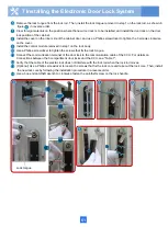
• The anti-theft screw can be replaced only after the electric lock is powered on. Before replacing the anti-theft screw, use
the access card or user identity card to check whether the door can be unlocked.
• The electric lock core and anti-theft screw must be properly installed. Otherwise, the electronic door cannot protect the
cabinet.
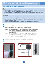
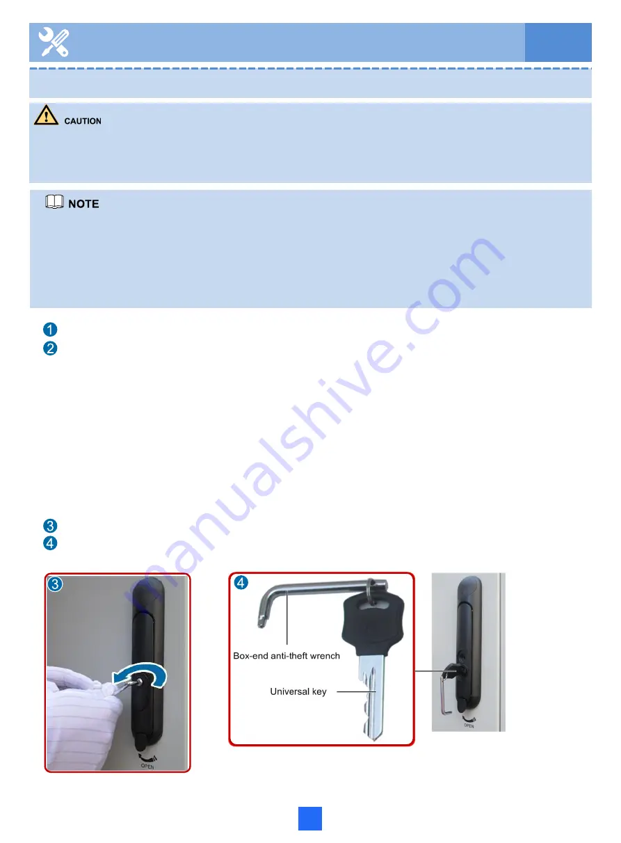
Use a box-end anti-theft wrench to anti-clockwise loosen the anti-theft screw on the lock.
Use an authorized access card or a universal key to open the electric lock.
• The recommended way of delivering the SPS security keys is as follows: The SPS security keys and electric lock cores are
separately packed and delivered together with the SPS.
• Before completing the site deployment, configure CCU information such as the IP address, mask, NMS, and authority. In
addition, record the name of the site where the cabinet is installed, serial numbers of the SPS security keys, and serial
numbers of the electric lock cores.
• Steps 1 and 2 are recommended steps and you can perform these 2 steps based on the site requirements.
Deliver the SPS security keys to the Security Department, and deliver the electric lock cores to each
site together with the cabinet based on the allocation rule.
Replace the electric lock cores at a site based on either of the following scenarios:
Scenario 1 If the power supply of the site has been set up and the cabinet can be powered on and work
normally, replace the electric lock cores and anti-theft screws. Then, the customer can
open the cabinet doors using the authorized access card and install and maintain service
devices in the cabinets.
Scenario 2 If the power supply of the site has not been set up and the cabinet cannot be powered on,
hand over the electric lock cores, anti-theft screws, and universal keys to the customer.
When the power supply of the site is available, the customer can assign an engineer to the site to
replace the electric lock cores and anti-theft screws.
7 Installing the Electronic Door Lock System
7.5 Installing the Anti-Theft Screw
Summary of Contents for F01T500
Page 1: ...HUAWEI TECHNOLOGIES CO LTD F01T500 Quick Installation Guide Issue 07 Date 2017 05 03 ...
Page 19: ...With battery cabinet 4 Installing the Cabinet on a Concrete Pedestal 14 ...
Page 23: ...18 Unit mm 4 Installing the Cabinet on a Concrete Pedestal ...
Page 25: ...20 4 Installing the Cabinet on a Concrete Pedestal ...
Page 27: ...22 4 Installing the Cabinet on a Concrete Pedestal ...
Page 38: ...33 With power meter box ...
Page 40: ...35 With power meter box AC power cables AC power cables ...
Page 44: ...39 6 Routing Cables 6 3 Diagram of Cable Connections Between the RPS and MDF RPS Power Supply ...
Page 51: ...46 Route the input Cables of the AC RPR power supply 6 Routing Cables ...
Page 83: ...14 FAQs for Installation 78 ...
Page 84: ...15 FAQs for Installation 79 ...

