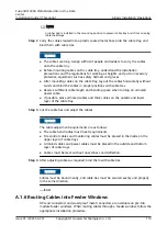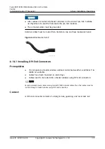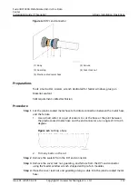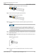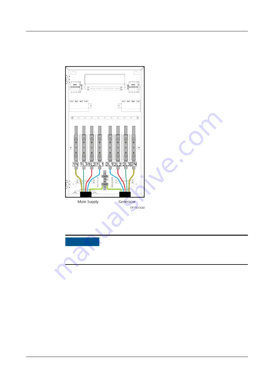
Step 4 Route the external input power cables into the power PDB through the cable holes
at the bottom, and route them out along the cable bridge above the cable holes.
Figure 9-2 Connecting input power cables for the power PDB
Step 5 Connect the cables by following the instructions in
NO TICE
After connecting the cables, seal the two cable holes at the bottom of the power
PDB using waterproof sealing putty.
Step 6 Reinstall the transparent cable protection panel, and close the door of the power
PDB.
----End
9.2 (Optional) Connecting Generator Start/Stop Cables
(ATS Input)
Procedure
Step 1 Connect the generator start/stop cables to the terminals on the XT2 terminal
block.
FusionDC1000A Prefabricated All-in-One Data
Center
Installation Guide (IT Scenario)
9 Installing Cables Outside the Pre-fab. Module
Issue 01 (2021-04-20)
Copyright © Huawei Technologies Co., Ltd.
98


