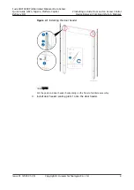
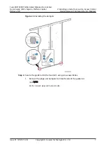
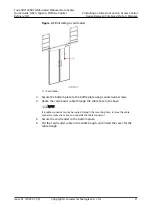


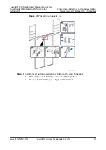
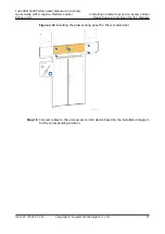
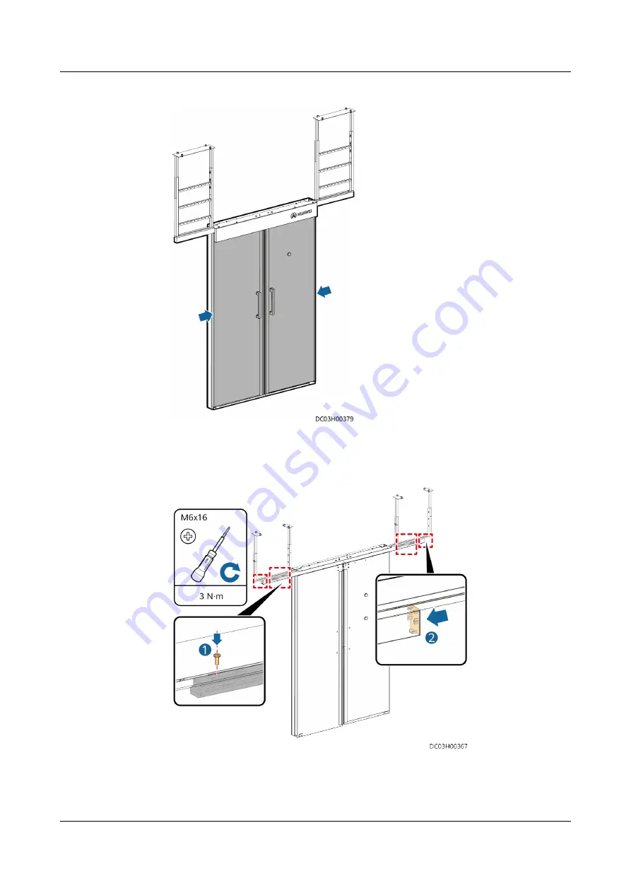
Figure 2-12 Installing the aisle door
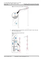
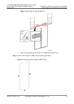
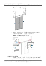
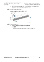
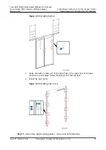
2. Install the removed bumpers from both ends of the guide rail, secure the
bumpers, and install plugs at both ends of the guide rail.
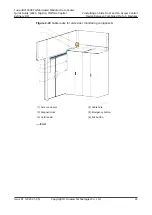
Figure 2-13 Installing the bumpers and plugs
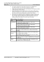
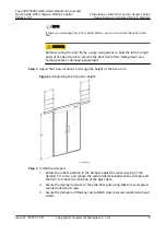
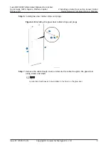
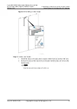
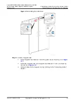
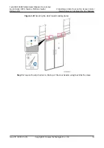
Step 10 Level the aisle door.
1. Adjust the height of the fixed arm, and verify that the upper surface of the
guide rail is flush with the upper surface of the door header.
FusionDC1000B Prefabricated Modular Data Center
Quick Guide (2020, Nigeria, Platform Capital
Refinery DC)
2 Installing an Aisle Door and an Access Control
Device Between Combined Pre-fab. Modules
Issue 01 (2021-01-05)
Copyright © Huawei Technologies Co., Ltd.
13
Summary of Contents for FusionDC1000B
Page 45: ......
Page 46: ......
Page 51: ......
Page 52: ......
Page 53: ......
Page 54: ......
Page 55: ......
Page 56: ......
Page 59: ......
Page 60: ......
Page 61: ......
Page 68: ......
Page 69: ......
Page 70: ......
Page 71: ......
Page 72: ......
Page 73: ......
Page 77: ......
Page 82: ......
Page 83: ......
Page 92: ......
Page 93: ......
Page 94: ......
Page 98: ...Window CB DH 1 Window CB PR B1 ECC NO M001 Monitoring Device Layout Diagram ...
Page 110: ...NO F002 Fire Extinguishing System Conceptual Diagram CE ...
Page 111: ...NO F002 Fire Extinguishing System Conceptual Diagram CE ...
Page 112: ...NO F002 Fire Extinguishing System Conceptual Diagram CE ...
Page 113: ...NO F002 Fire Extinguishing System Conceptual Diagram CE ...
Page 114: ...NO F002 Fire Extinguishing System Conceptual Diagram CE ...
Page 115: ...NO F002 Fire Extinguishing System Conceptual Diagram CE ...
Page 116: ...NO F002 Fire Extinguishing System Conceptual Diagram CE ...
Page 117: ...NO F002 Fire Extinguishing System Conceptual Diagram CE ...
Page 118: ...NO F002 Fire Extinguishing System Conceptual Diagram CE ...
Page 119: ......
Page 120: ...Window CB DH 1 Window CB PR B1 EXIT Exit DH 3 NO F003 Emergency Exit Diagram ...


