FusionModule1000B Air-Cooled IT Solution
Maintenance Guide
6 Parts Replacement
Issue 02 (2017-01-10)
Huawei Proprietary and Confidential
Copyright © Huawei Technologies Co., Ltd.
159
Preparations
Tools: Phillips screwdriver, protective gloves, step ladder
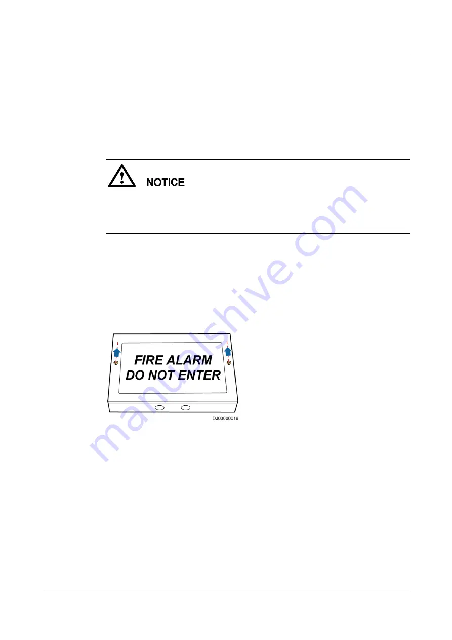
Materials: spare warning sign indicator
Documents: fire extinguishing device layout diagram (CE)
Skill requirement: fire engineer
For the diagrams, see the initial configuration parameter manual for the solution in use.
Before replacing the warning signs, inform the related administrative departments of the
temporary downtime of the fire extinguishing system. After the replacement, inform the
administration department that the system has become operational.
Procedure
Step 1
Disconnect the battery cables, and switch off the input circuit breaker of the extinguishant
control panel.
Step 2
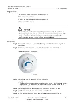
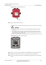
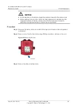
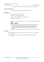
Loosen the screws securing the warning sign and its base using a Phillips screwdriver, and
remove the cover of the warning sign.
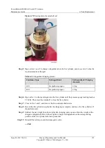
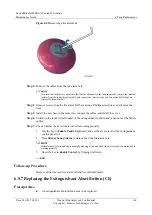
Figure 6-80
Removing screws
Step 3
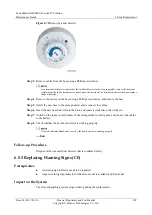
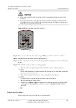
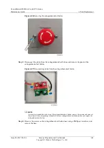
Remove the cables from the warning signs, and label the cables.
Step 4
Remove the screws on the base using a Phillips screwdriver, and remove the base.
Step 5
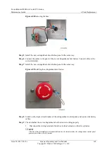
Install the new warning sign base in the same way, and connect the cables.
Step 6
Install the warning sign cover.
Step 7
Switch on the input circuit breaker of the extinguishant control panel, and connect the battery
cables.
Step 8
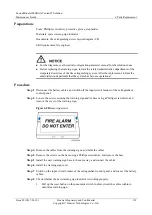
Check whether the new warning sign indicator is working properly.
1.
Pull up the reset button on the pneumatic switch to short-circuit the cables within to
simulate a warning sign.








![Lambrecht Ser[LOG] Operator'S Manual preview](http://thumbs.mh-extra.com/thumbs/lambrecht/ser-log/ser-log_operators-manual_3390951-001.webp)


