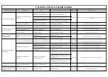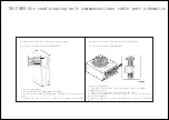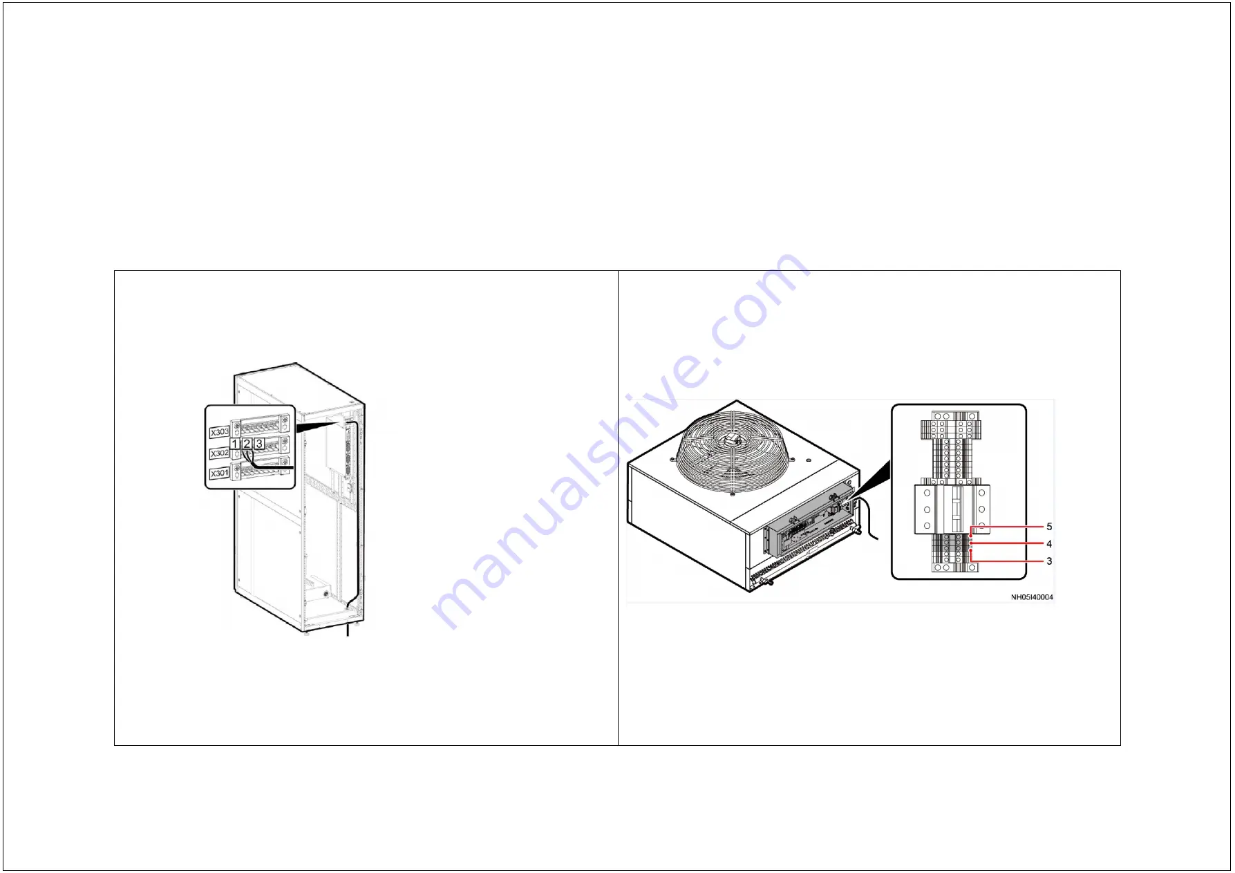
Air Conditioner Indoor Unit Wiring Port Layout Diagram
Technical requirements:
1. Use a 3x16 AWG cable (BOM number: 25030361).
2. Crimp cord end terminals (BOM number: 14170097) at both ends of the
cable.
3. Connect the cable to ports 1, 2, and 3 of the signal terminal X302.
Air conditioner model: 42 kW NetCol5000-A042
Air Conditioner Outdoor Unit Wiring Port Layout Diagram
Technical requirements:
1.
The signal cable between indoor and outdoor units is an RS485
communications cable.
2.
Crimp cord end terminals at both ends of the cable.
3.
Connect the communications cable to ports 3, 4, and 5 of the outdoor
unit signal terminal.
4. Black corresponds to 3, white corresponds to 4, and green corresponds
to 5.
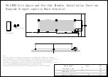
NO.C004 Air conditioning unit communications cable port schematic
Summary of Contents for FusionModule1000A40 ICT Solution
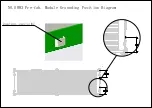
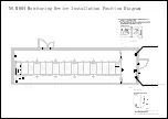
Page 11: ...NO S003 Pre fab Module Grounding Position Diagram ...
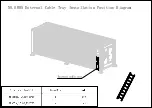
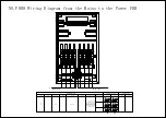
Page 12: ...NO S005 External Cable Tray Installation Position Diagram ...
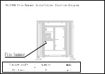
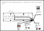
Page 13: ...NO S006 Fire Hammer Installation Position Diagram ...
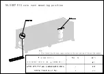
Page 14: ...NO S007 FIG rain eave mounting position ...
Page 15: ...Pipe window NO S004 Pre fab Module Pipe Installation Position Diagram ...

