background image


HES-319M Installation 

12 

Base Station Restrictions 

The HES-319M operates in the 3,400MHz to 3,600MHz range and cannot be used with base stations that 
operate above 3,600MHz.  The WiMAX Base Station ID list available from the Xplornet University WiMAX 
library shows the base stations that can communicate with the HES-319M.   


If you are planning to install an HES-319M, verify that there is a compatible base station 
within range of your customer’s site – before you leave for the site. 


Summary of Contents for HES-319M

Page 1: ...Version 1 1 Publication Date 12 Apr 13 HES 319M Installation ...

Page 2: ... Shipped 7 HES 319M ODU 8 HES 319M ODU Signal Strength Indicators 9 HES 319M IDU 10 Static IP Addresses 11 Base Station Restrictions 12 3 Mounting the HES 319M ODU 13 Other mounting options 16 4 Installing Cables and Grounds for the HES 319M 17 Approved and Unacceptable Building Ground Points 19 Shaving the RJ 45 Connector Boot on the Cat5e PoE Cable 20 Connecting the Surge Suppressor to the Build...

Page 3: ...lation 3 5 Aligning the HES 319M 31 Rescanning for Base Stations 32 Quality of Installation Parameters 34 Alignment and Acceptance 35 Identifying the Base Station 38 6 Connecting Your Customer s Computer to the CPE 39 ...

Page 4: ...er Premise Installation guide for information on Preparing for a site visit Performing a site survey General mounting guidelines and requirements Service activation Quality of Installation tables Safety standards Refer to this guide for information on HES 319M components interfaces and indicators HES 319M support for static IP addresses HES 319M mounting instructions HES 319M cabling and grounding...

Page 5: ...ll base stations Supported by all base stations On base stations operating from 3475MHz to 3600MHz ODU Location Requirements The location requirements detailed in the WiMAX Customer Premise Equipment Installation guide apply to all Mounting Mount so sides are at 45 to the horizontal Mount so sides are at 45 to the horizontal Mount so top and bottom are at 0 to the horizontal with interface side on...

Page 6: ...Channel Bandwidth and the Rate Plan WMI Parameter for QoI RSSI Level RSSI RSSI Signal Strength WMI Parameter for QoI CINR Level CINR reuse 1 CINR Link Quality Display of QoI Levels WMI CINR and RSSI LEDs at ODU CINR Telephone tones CINR WMI CINR and RSSI LEDs at ODU RSSI WMI CINR and RSSI Activation Installer Portal The same for all except there is a firmware upgrade process with the BreezeMAX PRO...

Page 7: ...S 319M CPE is shipped in one box that contains The outdoor unit A or ODU with sealing gland assembly B The indoor unit C or IDU with AC power cord D A 6ft 1 8m Ethernet cable E A mounting kit F A grounding kit G Contents may not appear exactly as shown ...

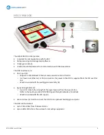
Page 8: ... over Ethernet or PoE connection the power to the ODU is supplied from the IDU over this link o Weather sealed with the sealing gland assembly B Signal Strength LEDS C o Five LEDs indicate the strength of the signal received from the base station Refer to the next topic HES 319M ODU Signal Strength Indicators for details o Weather sealed with the LED cap D Ground screw E Used to connect the ODU to...

Page 9: ...RSSI Received Signal Strength Indicator of the signal from the base station You use the signal strength indicators when you align the ODU details are provided in the chapter Aligning the HES 319M Signal Strength RSSI Signal Strength LEDs 50dBm 60dBm to 50dBm 70dBm to 60dBm 80dBm to 70dBm 90dBm to 80dBm 90dBm ...

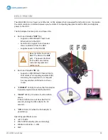
Page 10: ...ODU B Be very careful to connect ONLY the ODU to the OUT port The power destined for the ODU can destroy customer equipment in milliseconds RJ 45 port labelled IN C o Supports a 10 100 BaseT Ethernet link to the customer s computing equipment D Generally the equipment is a computer but may also be a LAN device such as a router CONNECT LED E On when the PoE adapter is powered up and connected to th...

Page 11: ...llation 11 Static IP Addresses Static IP addresses are not supported on the HES 319M If you are planning to install an HES 319M be sure your customer has not ordered a static IP address before you leave for the site ...

Page 12: ...tations that operate above 3 600MHz The WiMAX Base Station ID list available from the Xplornet University WiMAX library shows the base stations that can communicate with the HES 319M If you are planning to install an HES 319M verify that there is a compatible base station within range of your customer s site before you leave for the site ...

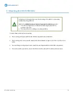
Page 13: ...uipment to a customer s premise The instructions for installing a mounting platform Consider these points before proceeding The mounting kit shipped with the HES 319M is required to mount the ODU The mounting kit can be used with masts poles whose diameter ranges in size from 1 to 2 5in 2 5 to 6 4cm You need the grounding kit wire and screw that was shipped with the HES 319M or equivalent To ensur...

Page 14: ... for the parallel position 1 Position the bracket so that the flange with 15 faces up 2 Hold the bracket against the pole and feed the U bolt through the bottom holes in the bracket If the 15 flange is up feed the U bolt through the top holes for a parallel mount 3 Spin an M6 nut on each arm of the U bolt 4 Move the kit to the desired position on the pole and tighten the nuts ...

Page 15: ...e RJ 45 port faces down 6 Slide the studs into the holes and spin M6 nuts on each bolt 7 Tighten the nuts firmly but do not over tighten 8 Thread the screw provided with the grounding kit through one of the ring lugs on the ground wire and into the threaded hole on the back of the ODU just below the ground symbol 9 Tighten the screw ...

Page 16: ...HES 319M Installation 16 Other mounting options Alternate mounting options are illustrated below Note which flange is up 15 or 15 and which holes the U bolt goes through upper or lower ...

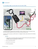
Page 17: ... task are provided in following topics In all topics cable is synonymous with Cat5e cable In the diagrams the Cat5e cable is shown as red for illustrative purposes only Task List 1 Confirm that the mount location satisfies all requirements listed in the Location Requirements Checklist in the WiMAX Customer Premise Equipment Installation guide 2 Review the grounding standards 3 Shave the RJ 45 conn...

Page 18: ...e install two ground straps on the pole a hand s width apart 8 Install a ground wire between the surge suppressor and the dual ground lug or the lower ground strap 9 Install a ground wire between the ground screw on the ODU and the dual ground lug or the upper ground strap 10 Install a Cat5e cable between the surge suppressor and the IDU 11 Install the supplied Ethernet cable between the IDU and y...

Page 19: ...sures Never drill into an electrical service panel A metal conduit or raceway of the electrical service A grounded interior metal water pipe An I beam clamp on a grounded structural steel member Unacceptable ground points are Conduit on the load side of a building enclosure A cut off switch or a condensation pipe on a Heating Ventilation Air Conditioning or HVAC system Steel roof trusses Metal roo...

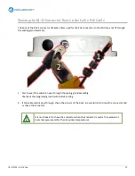
Page 20: ...gland assembly 1 Test to see if the cable can pass through the sealing gland assembly Peel back the integrated ground wire before testing 2 If the cable cannot pass through shave the corners of the boot Be careful not to break the connector tab or shave the connector It is much easier to shave the connector when the connector is warm for example at room temperature rather than at winter temperatur...

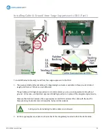
Page 21: ...he distance refers to the total wire length not the straight line path 2 If necessary remove the surge suppressor circuit board to expose the two mounting holes 3 Fasten the surge suppressor to a solid surface as close to the planned point of entry as possible Ensure that the side with the cable grommets faces down 4 Reinstall the circuit board 5 Remove the rubber cable grommets and make a small v...

Page 22: ...et approved single cable clips every 24in 60cm to secure the wire to the building 8 Cut the wire so that it can reach through the most convenient grommet to the brass nut on the same side as the grommet 9 Strip away about 1in 3cm of insulation 10 Pass the wire through the grommet 11 Loosen the nut and wrap the stripped wire clockwise around the brass post between the two brass washers The surge su...

Page 23: ... cable with integrated ground wire is recommended you can use an equivalent cable without ground In this case use Xplornet approved 12AWG ground wire in place of the integrated ground wire Measure the distance between the surge suppressor and ODU and select the cable with the best fit Measure along horizontal and vertical paths but avoid sharp bends Cutting and re terminating the Cat5e cable is no...

Page 24: ...ips every 24in 60cm to secure the cable and integrated ground wire to the building If you are using Xplornet approved 12AWG ground wire rather than an integrated wire use single cable clips on both the cable and wire 9 Run the cable to the ODU RJ 45 port 10 Coil any excess cable When all connections have been made secure the coil as close to the ODU as is practical 11 At the ODU RJ 45 port remove ...

Page 25: ...to its centre along its length to allow this When using Cat5e cable with integrated ground wire separate enough of the ground wire from the cable so that the rubber bushing goes over the cable only and only the cable enters the sealing gland assembly f Push the rubber bushing along the cable until it is firmly seated in the sealing gland base g Install the sealing gland nut Hand tighten firmly you...

Page 26: ...ectrical connection For a pole mount platform install two ground straps around the pole near the ODU about a hand s width apart Ensure that the ground strap material is the same as the pole material galvanized steel for example A metal mismatch can cause a galvanic reaction that corrodes the metal 16 If you are using the ground wire supplied with the CPE then you attached one end of the ground wir...

Page 27: ...actice to cut the wire about 6in 15cm longer than the minimum required 19 Strip about 1 2in 1 cm of insulation from the wire 20 Insert the stripped wire into the unused terminal of the dual ground lug or in the terminal of the lower ground strap 21 Tighten the terminal screw 22 Secure the Cat5e cable and ground wire to the mounting platform using cable ties every 6in 15cm ...

Page 28: ...50ft 15m and 75ft 23m Measure the distance between the surge suppressor and IDU and select the cable with the best fit Remember to allow for a drip loop Cutting and re terminating the Cat5e cable is not allowed 2 At the surge suppressor slip the Cat5e cable through the grommet used for the building ground wire and plug the cable into the RJ 45 port 3 Run the cable to the point of entry creating a ...

Page 29: ...ht Avoid sharp bends Use Xplornet approved single cable clips every 24in 60cm to secure the cable to the building 5 Coil excess cable inside the building in an out of the way location preferably out of sight 6 Unpack the IDU place it in location and plug the Cat5e cable into the port labelled OUT ...

Page 30: ...e customer s equipment only after activating the service 1 Plug one end of the supplied Ethernet cable into the RJ 45 port on the IDU labelled IN 2 Plug the other end into the Ethernet port on your computer 3 Plug the power cord into the IDU and a 120VAC power source 4 Power up your computer You are ready to align the ODU ...

Page 31: ...ion 31 5 Aligning the HES 319M This chapter explains how to align the HES 319M with a base station and verify that the signal quality is within acceptable limits Always rescan for base stations before starting alignment ...

Page 32: ...e the CPE to rescan for base stations to ensure that the CPE is registered with the best base station at its current location and direction You must force the CPE to rescan for base stations anytime the CPE has been powered up and then moved to another location or pointed in another direction at the same location You can force a rescan by Powering down the ODU Rebooting the CPE through the Web Man...

Page 33: ...the AC power cord at the IDU a OR Disconnect the PoE Cat5e cable from the OUT port at the IDU b OR Disconnect the PoE Cat5e cable from the RJ 45 port at the ODU c 2 Wait 10 seconds then restore power The CPE performs a rescan Wait about two minutes for the CPE to reconnect with a base station ...

Page 34: ...rs have been defined for the WiMAX service and acceptable values for the QoI parameters are set for each rate plan A service is unacceptable if a measured value fails to meet the specified value The QoI parameters are provided as an appendix to the WiMAX Customer Premise Equipment Installation guide Part of your site preparation was to download the guide to your computer and to record your custome...

Page 35: ...HCP you must do so now Refer to the DHCP topic in the WiMAX Customer Premise Equipment Installation course or guide When you have configured your computer for DHCP 1 Have the applicable QoI levels available as well as the URL and login credentials of the HES 319M WMI 2 At the ODU point the ODU along the line of sight to the base station you chose during your site survey 3 Rescan for base stations ...

Page 36: ... base station If Device Status does not go to Connected i Check all cables and connectors between your computer and the ODU ii At the ODU rescan for base stations and confirm that one or more LEDs are on iii At the WMI if Device Status is still not Connected contact the Dealer Support Group 1 866 841 6004 14 When Device Status is Connected and Connection Status is Normal or Idle compare the channe...

Page 37: ...escan for base stations and repeat the alignment and acceptance procedure f If the quality is still unacceptable or there is only one base station contact the Dealer Support Group 1 866 841 6004 RSSI Too High Is the RSSI level better than 40 As an example 39 is better than 40 If yes change the alignment so that the RSSI falls to 40 or slightly worse for example 41 or 42 This is necessary to avoid ...

Page 38: ...s a guest 4 Click OK The System Status window opens 5 Scan to the bottom of the window and locate the BSID number BSID stands for Base Station Identifier The first six digits of the BSID are the same for all Xplornet base stations The seventh to tenth digits identify the site The last two digits identify the sector Digits can be letters or numbers 6 Download and open the Base Station ID list from ...

Page 39: ...y old equipment you may not be able to realize a positive outcome If you choose to connect your customer s computer 1 Ensure that your customer s computer is configured for DHCP operation refer to the DHCP topic in the WiMAX Customer Premise Equipment Installation course or guide 2 When you have configured the computer for DHCP plug the supplied Ethernet cable into your customer s computer and the...

Page 40: ...b Use a web page with frequently updated content to ensure that the browser is actually surfing the web and not accessing old content saved on the computer For examples try cbc ca or ctv ca If you can surf you are done If you cannot and you are not familiar with relevant troubleshooting procedures refer the customer to Xplornet Technical Support 1 866 841 6001 support xplornet com ...

Reviews: