


iManager NetEco 6000
Device Installation and Commissioning Guide
3 Installing Devices
Issue 03 (2019-03-10)
Copyright © Huawei Technologies Co., Ltd.
35
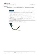
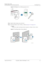
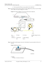
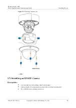
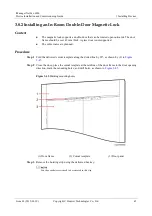
Figure 3-31
Installing the VCN500
Step 4
Connect the VCN500 power cable to the PDU2000.
----End
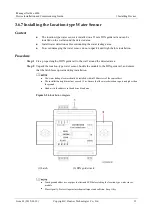
3.7.2 Installing an IPC6325 Camera
Prerequisites
A camera and tools for installing it have been prepared.
A network cable for connecting the camera to the switch has been prepared.
The switch has been normally powered on.
Context
This topic describes how to install and commission a camera in a room. Two persons are
required for the commissioning.
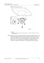
Cameras can be installed on different objects based on scenarios. This section describes
how to install a camera on the ceiling.
The camera described in this section can be installed only on a suspended ceiling if
on-ceiling installation is required.
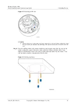
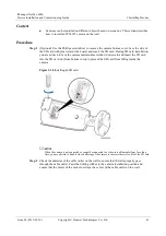
Procedure
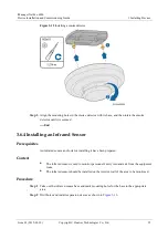
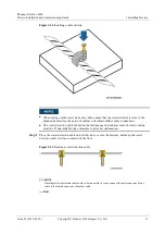
Step 1
(Optional) Use a Phillips screwdriver to remove the transparent cover, install the SD card.


