iManager NetEco 6000
Device Installation and Commissioning Guide
4 Connecting Monitoring Cables to Devices
Issue 03 (2019-03-10)
Copyright © Huawei Technologies Co., Ltd.
70
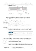
Figure 4-14
VCN500 ports
(1) Ground point
(2) GE2 port
(3) Power switch
(4) Power input port
(5) GE1 port
Step 2
Connect the other end of the network cable to the Ethernet port on the LAN switch.
----End
4.2.3.2 Connecting a Monitoring Cable to a Camera
Prerequisites
A network cable used for monitoring is prepared.
An idle network port supporting the PoE function is available on the LAN switch.
The camera has the PoE function.
Procedure
Step 1
Connect the monitoring port on the camera to any network port on the switch by using the
network cable. The switch is powered by using the power over Ethernet (PoE) technology.
Device cables not mentioned in the document do not need to be connected onsite and should
be insulated only.
----End
4.2.4 Connecting the Smart Cooling Product Monitoring Cable
Prerequisites
A network cable used for monitoring is prepared.
Context
When NetCol5000C-65kW&80kW, NetCol5000-A042/A035/A020/C030/C070/C150 connect
to the NetEco over Modbus-TCP, connect cables by referring to this section.


