Step 6
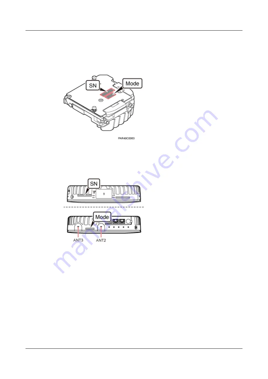
Remove the SN label and mode label on the surface of the RF daughter board, as shown in
.
Figure 6-4
Removing the SN label and mode label
Step 7
Attach the removed SN label to the corresponding position for S2 label on the nameplate side
of the pRRU housing and the mode label to a position (for the label of slot S2 on the side of the
pRRU housing) between antenna ports ANT2 and ANT3, as shown in
.
Figure 6-5
Attaching the SN label and mode label
Step 8
Close the pRRU housing and tamp each side of the housing until a click is heard. Ensure that
the groove gaps between the front and back housings are evenly distributed. Use the M4 Phillips
screwdriver to tighten the Phillips screw on the housing with a torque of 1.4 N•m, as shown in
.
LampSite
Installation Guide
6 Appendix
Issue 02 (2014-05-27)
Huawei Proprietary and Confidential
Copyright © Huawei Technologies Co., Ltd.
94


