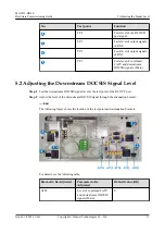
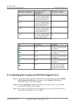
background image

MA5833-DD60

Hardware Commissioning Guide

Issue

01

Date

2018-12-26

HUAWEI TECHNOLOGIES CO., LTD.

Summary of Contents for MA5833

Page 1: ...MA5833 DD60 Hardware Commissioning Guide Issue 01 Date 2018 12 26 HUAWEI TECHNOLOGIES CO LTD ...

Page 2: ...s document may not be within the purchase scope or the usage scope Unless otherwise specified in the contract all statements information and recommendations in this document are provided AS IS without warranties guarantees or representations of any kind either express or implied The information in this document is subject to change without notice Every effort has been made in the preparation of th...

Page 3: ...ioning the Output Optical Power of the Optical Transmitter 7 5 Adjusting the Signal Level 9 5 1 Adjusting the CATV Signal Level 9 5 2 Adjusting the Downstream DOCSIS Signal Level 11 5 3 Adjusting the Upstream DOCSIS Signal Level 12 6 Checking Device Running 15 MA5833 DD60 Hardware Commissioning Guide Contents Issue 01 2018 12 26 Copyright Huawei Technologies Co Ltd ii ...

Page 4: ...cator is on when the power supply is within the specified range l Alternatively test whether the voltage on the test point of the 12 V DC and 34 V DC power supply meets requirements To do so adjust the multimeter for the DC voltage test connect the black probe of the multimeter to the metal place on the front panel and connect the red probe to the test point of the 12 V DC and 34 V DC power supply...

Page 5: ...Voltage Test Points and Indicators on MA5833 MA5833 DD60 Hardware Commissioning Guide 1 Measuring the 60 V AC Output Voltage Issue 01 2018 12 26 Copyright Huawei Technologies Co Ltd 2 ...

Page 6: ...ritical value the MA5833 can be functional for a short period of time To ensure that the MA5833 is functional for a long period of time adjust the receive optical power Step 1 Set the wavelength of an optical power meter to 1490 nm and use it to measure the output power on optical fibers Step 2 If the test result exceeds the preceding range use an optical attenuator on the OLT side to decrease the...

Page 7: ...odules of different types used in the same upstream direction Specifications of the actual optical module prevail l If the test result exceeds the upper limit of the Rx optical power optical attenuator can be added on the ONU side to reduce the input optical power of the MA5833 End MA5833 DD60 Hardware Commissioning Guide 2 Checking Upstream Optical Port Optical Power Issue 01 2018 12 26 Copyright...

Page 8: ...tage Obtain the optical power from the following table based on the measured voltage Figure 3 1 Step 2 The input optical power ranges from 8 dBm to 3 dBm l If the input optical power is greater than 0 dBm add a fixed optical attenuator to decrease the receive optical power of the optical receiver l If the input optical power is less than 6 dBm check the output optical power of the optical transmit...

Page 9: ... No 2 1 58 No 1 1 26 No 0 1 Yes 1 0 79 Yes 2 0 63 Yes 3 0 5 Yes 4 0 4 Yes 5 0 32 Yes 6 0 25 Yes 7 0 2 No 8 0 16 No End MA5833 DD60 Hardware Commissioning Guide 3 Commissioning the Optical Power of the Optical Receiver Issue 01 2018 12 26 Copyright Huawei Technologies Co Ltd 6 ...

Page 10: ...l and connect the red probe to the optical power test point of the optical transmitter to measure the DC voltage Obtain the optical power from the following table based on the measured voltage Step 2 The output optical power ranges from 2 dBm to 4 dBm If the input optical power is out of this range replace the optical transmitter Output Optical Power dBm V DC or mW 4 2 51 3 2 MA5833 DD60 Hardware ...

Page 11: ... Optical Power dBm V DC or mW 2 1 58 End MA5833 DD60 Hardware Commissioning Guide 4 Commissioning the Output Optical Power of the Optical Transmitter Issue 01 2018 12 26 Copyright Huawei Technologies Co Ltd 8 ...

Page 12: ...put level through the attenuation bracket on the optical receiver l Alternatively adjust the CATV output level through the attenuation bracket for the level of the combined DS and CATV signals on the combiner NOTE When the attenuation bracket for the level of the combined DS and CATV signals on the combiner is adjusted the DS output level is adjusted End The following figure shows the location of ...

Page 13: ...ombined CATV and downstream DOCSIS signal of the RF OUT1 4 ATT2 Level of combined CATV and downstream DOCSIS signal of the RF OUT2 4 ATT3 Level of combined CATV and downstream DOCSIS signal of the RF OUT3 4 No Test point Function TP 1 Tests level of the RF OUT0 port signal TP 8 Tests level of the RF OUT1 port signal TP 9 Tests level of the RF OUT2 port signal MA5833 DD60 Hardware Commissioning Gui...

Page 14: ...evel at the test point of the RF OUT port Step 2 Adjust the level of the downstream DOCSIS signal through the attenuation bracket End The following figure shows the location of the test points and attenuation brackets For details see the following table Bracket to Be Adjusted Parameter to Be Adjusted Default value dB ATT4 Level of combined CATV and downstream DOCSIS signals Main 0 MA5833 DD60 Hard...

Page 15: ...the RF OUT3 port signal TP 7 Tests level of combined CATV and downstream DOCSIS signals Main 5 3 Adjusting the Upstream DOCSIS Signal Level Step 1 Confirm the CM side output level of the RF OUT port and record it as A Run the display cable modem extended tx power command to query Extended US TX Power A Upstream TX Power cable line attenuation Step 2 Run the cable upstream command to configure the ...

Page 16: ...gure shows the location of the test points and attenuation brackets on a combiner Bracket to Be Adjusted Parameter to Be Adjusted Default value dB ATT9 Level of upstream DOCSIS signal of the RF OUT3 0 ATT6 Level of upstream DOCSIS signal of the RF OUT0 0 ATT8 Level of upstream DOCSIS signal of the RF OUT2 0 ATT7 Level of upstream DOCSIS signal of the RF OUT1 0 No Test point Function TP 5 Tests lev...

Page 17: ...eam signals in RF OUT0 TP 12 Tests level of upstream signals in RF OUT2 TP 13 Tests level of upstream signals in RF OUT1 MA5833 DD60 Hardware Commissioning Guide 5 Adjusting the Signal Level Issue 01 2018 12 26 Copyright Huawei Technologies Co Ltd 14 ...

Page 18: ...rly working Indicators on the MA5833 DD60 and Indicator Descriptions Indicator Name Color Status Description PWR Power supply status indicator Green On The device is powered on Off The device is powered off MA5833 DD60 Hardware Commissioning Guide 6 Checking Device Running Issue 01 2018 12 26 Copyright Huawei Technologies Co Ltd 15 ...

Page 19: ... CM status indicator Green On A CM is online Off No CM is online EQAM EQAM status indicator Green On EQAM is functional Off EQAM is faulty LINK ACT PON l LINK link status indicator l ACT authenticati on or data status indicator Off The uplink port does not receive optical signals or an optical fiber is disconnected from the device Green l LINK On l ACT Blinking on for 0 25 s and off for 0 25 s rep...

Page 20: ... uplink port is excessively low Orange l LINK On l ACT On The input optical power of uplink port is excessively high LINK GE Link status indicator Green On The uplink optical port is receiving optical signals Off The uplink port does not receive optical signals or an optical fiber is disconnected from the device ACT GE Authentication or data status indicator Green Blinking on for 0 25 s and off fo...

Page 21: ...used Off This channel has not been used OPT TX0 TX1 RX0 RX1 Alarm indicator of the optical receiver transmitter Green On The optical power is less than the upper threshold and greater than the lower Red On The optical power is greater than the upper threshold Orange On The optical power is less than the lower threshold LINK TX0 TX1 RX0RX1 Power indicator of the optical receiver Green On The optica...

Page 22: ...itter is registering or insert the wrong optical receiver transmitter Off The power supply of the optical receiver transmitter is abnormal or the module is not optical receiver transmitter MA5833 DD60 Hardware Commissioning Guide 6 Checking Device Running Issue 01 2018 12 26 Copyright Huawei Technologies Co Ltd 19 ...

Reviews: