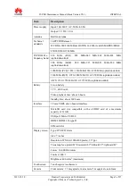
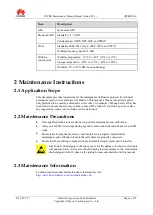
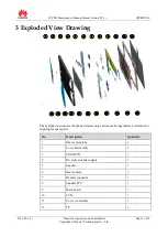
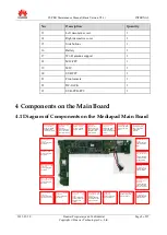
Huawei Mediapad S7-PRO, Maintenance Manual
Introducing the Huawei Mediapad S7-PRO, a cutting-edge tablet designed to revolutionize your multimedia experience. Enhance your device's lifespan with the comprehensive Maintenance Manual available for free download at 88.208.23.73:8080. Unlock the full potential of your Mediapad S7-PRO with this essential manual, ensuring efficient usage for years to come.
Share
Download


Reviews:
No comments
Related manuals for Mediapad S7-PRO
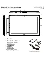
Iconia Tab 10
Brand: Acer Pages: 10
ICONIA W7
Brand: Acer Pages: 17
Iconia One 7 B1-730HD
Brand: Acer Pages: 52
Enduro T1
Brand: Acer Pages: 44
Iconia One 8
Brand: Acer Pages: 48
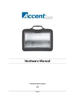
1000
Brand: Accent Pages: 37
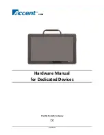
1400
Brand: Accent Pages: 42
M275
Brand: Gateway Pages: 78

T10+
Brand: Tobii Dynavox Pages: 32
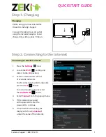
Tablet
Brand: Zeki Pages: 2
Tablet
Brand: Yarvik Pages: 20
Versa LitePad
Brand: NEC Pages: 29
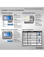
Toughbook U1 Ultra
Brand: Panasonic Pages: 2
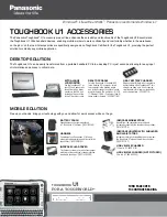
Toughbook U1 Ultra
Brand: Panasonic Pages: 2
CF-C1 Series
Brand: Panasonic Pages: 2
FZ-X1
Brand: Panasonic Pages: 27
FZ-S1 Series
Brand: Panasonic Pages: 71
FZ-M1 Series
Brand: Panasonic Pages: 18


