background image

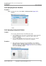
5.6.4 Querying Device Runtime

Procedure

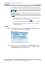
Step 1 On the home screen, choose Maint > Performance Maint

Figure 5-29

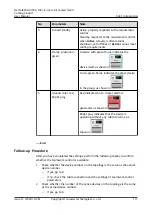
 is

displayed.

Figure 5-29 Performance maint screen

----End

5.6.5 Querying Component Status

Context

You can query component status in the following two ways.

Enter the Status screen. The control or running status of major components

such as the compressor, indoor fan, outdoor fan, electric heater, and

humidifier is displayed.

Enter the Device Details screen and then enter the menu of a specific

component. All parameters for the component are displayed.

Procedure

When viewing the component status through Status, choose Common

Functions > Status or Running > Status on the home screen. The general

component status screen is displayed. 

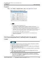
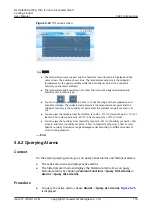
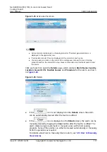
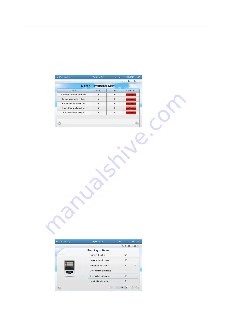
Figure 5-30

 shows the screen displayed

after choosing Running > Status.

Figure 5-30 General status

NetCol8000-A(050, 100) In-room Air Cooled Smart

Cooling Product

User Manual

5 ACC Introduction

Issue 12 (2020-10-28)

Copyright © Huawei Technologies Co., Ltd.

119

Summary of Contents for NetCol8000-A Series

Page 1: ...NetCol8000 A 050 100 In room Air Cooled Smart Cooling Product User Manual Issue 12 Date 2020 10 28 HUAWEI TECHNOLOGIES CO LTD ...

Page 2: ...s document may not be within the purchase scope or the usage scope Unless otherwise specified in the contract all statements information and recommendations in this document are provided AS IS without warranties guarantees or representations of any kind either express or implied The information in this document is subject to change without notice Every effort has been made in the preparation of th...

Page 3: ...ng product Disclaimer This product is professional equipment Its noise meets the requirements of GB T 19413 2010 Unitary air conditioners for computer and data processing room It is applicable to places where the common public office is not easy to touch If an office is set up near the equipment room sound insulation measures must be taken for the equipment room to meet the GB50174 2017 data cente...

Page 4: ...or unanticipated results NOTICE is used to address practices not related to personal injury Supplements the important information in the main text NOTE is used to address information not related to personal injury equipment damage and environment deterioration Change History Changes between document issues are cumulative The latest document issue contains all the changes made in earlier issues Iss...

Page 5: ... Cooled Smart Cooling Product User Manual Deleted descriptions about fan configurations Updated nitrogen injection and pressure preservation values Modified the controller section Modified the procedure for replacing an indoor fan Issue 03 2014 10 10 Modified the electric control box Issue 02 2014 07 30 Updated the document description Issue 01 2013 12 10 This issue is the first official release N...

Page 6: ...and Features 18 2 2 3 Monitoring System 19 2 2 4 Ports 19 2 3 Environment Specifications 20 2 3 1 Installation requirements 20 2 3 2 Environmental Requirements 20 2 4 Performance Parameters 21 3 Installation Guide 24 3 1 Installation Precautions 24 3 1 1 Precautions 24 3 1 2 Tools 25 3 1 3 Material Preparations 28 3 1 4 Structural Specifications 35 3 1 5 Installation Layout 36 3 1 6 Installation R...

Page 7: ...3 6 5 3 Connecting a Water Sensor Optional 68 3 6 6 Teamwork Networking and Monitoring 68 3 7 Removing the Protective Device from the NetCol8000 A 72 3 7 1 Removing the Protective Device from the Infrared Humidifier Lamp 72 3 7 2 Connecting the signal cable to the HWA cable terminal 73 3 7 3 Removing the Sheet Metals for Transporting the Compressor 75 3 8 Installation Verification 76 4 Power On Co...

Page 8: ...ical Alarms 122 5 7 2 Deleting Logs 123 5 7 3 Exporting Data 123 5 7 4 Clearing the Runtime 126 5 7 5 Calibrating a Sensor 126 5 7 6 Calibrating the Screen 127 5 8 How to Perform Quick Settings 129 5 9 How to Set the Language Date or Time 129 5 10 How to Change a Password 130 5 11 How to Restore the Initial Password 131 5 12 How to Troubleshoot the Fault When the System Is in Upgrade Mode 132 5 13...

Page 9: ...acing the Filters 183 7 4 2 Replacing an Indoor Fan 184 7 4 3 Replacing a Compressor 188 7 4 4 Replacing the Infrared Humidifier Lamps 191 7 4 5 Replacing Electrical Heaters 197 A Support Specifications 199 B Electrical Control Boxes 201 C Acronyms and Abbreviations 203 D Electrical Schematic Diagram NetCol8000 A050 204 E Electrical Schematic Diagram NetCol8000 A100 205 F Controller Menu Structure...

Page 10: ...ollow local laws and regulations when installing operating or maintaining the equipment The safety instructions in this document are only supplements to local laws and regulations Huawei will not be liable for any consequences of the following circumstances Operation beyond the conditions specified in this document Installation or use in environments which are not specified in relevant internation...

Page 11: ...ation operation and maintenance Before handling a conductor surface or terminal measure the contact point voltage and ensure that there is no risk of electric shock After installing the equipment remove idle packing materials such as cartons foam plastics and cable ties from the equipment area In the case of a fire immediately leave the building or the equipment area and turn on the fire alarm bel...

Page 12: ...d during equipment transportation or installation in a timely manner Equipment with scratches cannot be exposed to an outdoor environment for a long period of time Before operations ensure that the equipment is firmly secured to the floor or other solid objects such as a wall or an installation rack Do not use water to clean electrical components inside or outside of a cabinet Do not change the st...

Page 13: ...essionals personnel who are trained or experienced in equipment operations and are clear of the sources and degree of various potential hazards in equipment installation operation maintenance Trained personnel personnel who are technically trained have required experience are aware of possible hazards on themselves in certain operations and are able to take protective measures to minimize the haza...

Page 14: ...cilities must be performed by qualified personnel Cabling When routing cables ensure that a distance of at least 30 mm exists between the cables and heat generating components or areas This prevents damage to the insulation layer of the cables Do not route cables behind the air intake and exhaust vents of the equipment Ensure that cables meet the VW 1 or ZB flame spread rating requirements or high...

Page 15: ...ckaging materials before storing or transporting them Figure 1 1 Wearing an ESD wrist strap Neutral Ground Voltage It is recommended that the three phase loads be equalized and the neutral ground voltage be kept at less than 2 V to meet power distribution requirements 1 4 Installation Environment Requirements To prevent fire due to high temperature ensure that the ventilation vents or heat dissipa...

Page 16: ...ts Wear personal protective equipment such as the safety helmet and safety belt or waist rope and fasten it to a solid structure Do not mount it on an insecure moveable object or metal object with sharp edges Make sure that the hooks will not slide off Set a restricted area and eye catching signs for working at heights to warn away irrelevant personnel Carry the operation machinery and tools prope...

Page 17: ... fiberglass ladders when you need to perform live working at heights When a step ladder is used ensure that the pull ropes are secured and the ladder is held firm Before using a ladder check that it is intact and confirm its load bearing capacity Do not overload it Ensure that the ladder is securely positioned The recommended angle for a ladder against the floor is 75 degrees as shown in the follo...

Page 18: ...les inside Metal shavings from drilling may short circuit boards inside the equipment Obtain the consent from the customer and subcontractor before drilling Wear goggles and protective gloves when drilling holes When drilling holes protect the equipment from shavings After drilling clean up any shavings that have accumulated inside or outside the equipment Moving Heavy Objects DANGER When removing...

Page 19: ...stem Safety Welding At least two persons are required on a welding site A welder must have a work permit A welding site must be free from inflammables Ensure that a fire extinguisher wet wiper and water container are available A burning welding torch must not be placed on a component or on the floor and must not be placed in a metal container with acetylene and oxygen Otherwise the gas may leak an...

Page 20: ...h other wastes that have a shell in European Union EU areas To avoid environment pollution and harm to human health wastes must be classified and recycled This also promotes resource reuse When recycling a device fill in the device information in the recycling collection system or contact your dealer for help The dealer can help you recycle devices in a safe and environment friendly way 1 7 Others...

Page 21: ...vironment specifications and performance specifications 2 1 Model Description The naming rule for the NetCol8000 A series products is as follows Figure 2 1 Naming rule for the NetCol8000 A series products NetCol8000 A 050 100 In room Air Cooled Smart Cooling Product User Manual 2 Product Description Issue 12 2020 10 28 Copyright Huawei Technologies Co Ltd 12 ...

Page 22: ... connects to two outdoor units In the standard configuration of the NetCol8000 A050 one indoor unit connects to one outdoor unit 2 2 1 Indoor Unit Appearance The NetCol8000 A100 has four front doors and the NetCol8000 A050 has two front doors The rear panel and side panels are secured by screws Figure 2 3 shows the NetCol8000 A100 indoor unit and Figure 2 4 shows the NetCol8000 A050 indoor unit Ne...

Page 23: ... consists of a cabinet compressor evaporator thermostatic expansion valve infrared humidifier indoor fan EC electrical heater dry filter and air filter NetCol8000 A 050 100 In room Air Cooled Smart Cooling Product User Manual 2 Product Description Issue 12 2020 10 28 Copyright Huawei Technologies Co Ltd 14 ...

Page 24: ...y brand features high reliability and a long service life It is configured with the high efficiency EC tilting centrifugal fan to be optionally selected Compared with a common fan a high efficiency EC fan saves 40 more energy The direct drive that the indoor fan adopts has higher transmission efficiency than the belt drive which reduces the belt replacement and routine checks Compared with the fan...

Page 25: ...r or warning are raised simultaneously the indicator status corresponds to the alarm with the highest severity level and the buzzer status corresponds to the unacknowledged alarm with the highest severity level Figure 2 5 Display panel 1 Indicator 2 Display panel Table 2 1 Indicator and buzzer status description Alarm Status Indicator Buzzer The device is operating properly or a warning is generat...

Page 26: ...served 2 FE fast Ethernet communications port 3 CAN communications port for the main control board and LCD 4 RS485_1 Reserved NetCol8000 A 050 100 In room Air Cooled Smart Cooling Product User Manual 2 Product Description Issue 12 2020 10 28 Copyright Huawei Technologies Co Ltd 17 ...

Page 27: ...NetCol8000 A to meet the temperature and humidity requirements The LCD on the controller allows you to set the parameters of the NetCol8000 A and query the status information When multiple NetCol8000 As work cooperatively the controller optimally distributes the heat load greatly lowers the power consumption provides backup and improves the reliability Features The controller has the following fea...

Page 28: ...t The NetCol8000 A series products can be networked over a controller area network CAN bus to perform the teamwork which efficiently save energy and prolongs the service life Figure 2 7 shows the networking diagram for the monitoring system Figure 2 7 Network diagram for the monitoring system 2 2 4 Ports The following table lists NetCol8000 A series product ports Table 2 3 Ports of the NetCol8000 ...

Page 29: ...g product Pipe routing mode Routing from the bottom or side Maintenance mode Front and side maintenance for smart cooling products Maintenance distance Front maintenance distance 800 mm side maintenance distance 600 mm 2 3 2 Environmental Requirements NOTE Do not install the smart cooling product near a noise sensitive place such as an office or a conference room Table 2 5 Environmental specificat...

Page 30: ...bove 1000 m For details see Table 2 6 Water requirements to the humidifier The sum of calcium and magnesium cannot exceed 600 mg L Table 2 6 Derating coefficients Altitude 0 1000 1500 2000 2500 3000 3500 4000 Density coefficien t 1 0 887 0 835 0 785 0 737 0 692 0 649 0 608 Air volume coefficien t 1 0 887 0 835 0 785 0 737 0 692 0 649 0 608 Cooling capacity coefficien t 1 0 940 0 909 0 878 0 846 0 ...

Page 31: ...nsions H x W x D mm 1980 x 2280 x 890 1980 x 1140 x 890 Gross Net weight kg 967 830 520 415 a Recommended to add the voltage regulator in the front end if the power exceeds this range Otherwise smart cooling product will generate frequency alarms and cannot run b Three phase voltage imbalance can cause large current at some winding of the motor resulting in overheating and may damage the motor For...

Page 32: ...ur The customer is advised to add a dehumidifier unconfigured NOTE The test condition is that the indoor dry bulb temperature is 24 C condensing temperature is 45 C and relative humidifier is 50 NetCol8000 A 050 100 In room Air Cooled Smart Cooling Product User Manual 2 Product Description Issue 12 2020 10 28 Copyright Huawei Technologies Co Ltd 23 ...

Page 33: ...the requirements before installation and whether reconstruction is required for routing water pipes and cables and constructing ventilation pipes For the detailed requirements see 3 1 6 Installation Requirements 2 Install the device according to the design drawing and reserve space for maintenance 3 Install downflow NetCol8000 As in the equipment room with a raised floor 4 It is recommended that t...

Page 34: ... 10 13 18 Torque wrench 10 13 18 Polyvinyl chloride PVC insulation tape Protective gloves Electrostatic discharge ESD gloves Claw hammer Wire stripper Needle nose pliers Diagonal pliers Combination pliers Measuring tape Torch Step ladder Sealant or seal tape for thermal insulation foam a locking pliers N A N A N A N A NetCol8000 A 050 100 In room Air Cooled Smart Cooling Product User Manual 3 Inst...

Page 35: ...ruck Crowbar Hanging rope Table 3 3 Pipe installation tools Appearance Parameter and Name Cutter Welding torch Silver braze with 5 silver welding rod Nitrogena Acetylene Oxygen Hot melt tool Sealant or seal tapeb Anhydrous industrial alcohol N A N A N A N A N A N A NetCol8000 A 050 100 In room Air Cooled Smart Cooling Product User Manual 3 Installation Guide Issue 12 2020 10 28 Copyright Huawei Te...

Page 36: ...nce adapting to the thread size with pipeline Maximum seal gap is less than 0 5 mm The maximum pressure is greater than 3 MPa Conforms to JB T7311 2008 engineering mechanical the anaerobic adhesive application technology specification profession standard Table 3 4 Electrical installation tools Appearance Parameter and Name Electrostatic discharge ESD gloves Insulation gloves Power cable crimping t...

Page 37: ...arations This section describes optional components If you have not purchased such optional components from Huawei prepare the following materials pipe components and supports humidifier water supply and drainage components and cables Configuration Indications of Mandatory Optional and Unconfigured in this document are as follows Mandatory mandatory configuration This material is provided by Huawe...

Page 38: ...r to measure its internal pressure As shown in Table 3 6 the saturation pressure that corresponds to the external surface temperature and calculate the deviation from the internal pressure If the deviation is more than 0 2 MPa the refrigerant is not in good condition Replace it Figure 3 1 Refrigerant detection Table 3 6 Mapping Between Saturation Temperatures and Pressure of R410A Saturation tempe...

Page 39: ...rter than 30 m the outer diameter of the gas pipe and liquid pipe should be 7 8in 22 23 mm and 5 8in 15 88 mm If L is between than 30 m and 60 m the outer diameter of the gas pipe and liquid pipe should be 1in 25 40 mm and 3 4in 19 05 mm NOTE L indicates the length of the one way liquid pipe To ensure the NetCol8000 A reliability make an oil trap every 5 m to 6 m along pipes in the vertical direct...

Page 40: ... mm Technical Requirements Remarks 1 7 8 inch oil trap Optional Φ22 x 1 0 The flaring inner diameter of the copper pipe is 22 4 mm and the necking outer diameter is 19 5 mm The surface of forming parts should not be uneven NetCol8000 A 050 100 In room Air Cooled Smart Cooling Product User Manual 3 Installation Guide Issue 12 2020 10 28 Copyright Huawei Technologies Co Ltd 31 ...

Page 41: ...ing inner diameter of copper pipe is 25 8 mm 6 3 4 inch inverted trap of liquid pipes Optional Φ19 05 x 1 0 The flaring inner diameter of copper pipe is 19 4 mm Humidifier Water Supply Pipe and Drainpipe Two humidifier water supply pipe modes are provided Rigid pipe Prepare rigid pipes and connectors same as parts 2 and 3 in A of Figure 3 3 Hose Prepare hoses and pagoda connectors same as parts 4 ...

Page 42: ...OTE Part 1 in the dot line box is a port on the equipment Part 5 hose clamp is mandatory Other parts need to be configured Pipe Support Preparations The following figure shows the support for refrigerant and water pipes Determine detailed specifications based on onsite situation Figure 3 4 Pipeline support NetCol8000 A 050 100 In room Air Cooled Smart Cooling Product User Manual 3 Installation Gui...

Page 43: ...cations Name Specifications Descriptions Quantity Shipped with Device NetCol8 000 A050 power cable Power cable 5 x 16 mm2 L1 L2 L3 N P E N A Terminals Common terminal conductor cross section 16 mm2 length 20 mm 30 A insertion depth 12 mm black L1 L2 L3 N 10 pcs Terminals Naked crimping terminal OT 16 mm2 M6 tin plating insulated ring terminal 12 10AWG yellow PE 3 pcs NetCol8 000 A100 power cable P...

Page 44: ...07 2 x T0 5 mm2 N A N A Needle Valve Before installation check that all needle valves have valve plugs If a needle valve has no valve plug install an R410A valve plug and tighten the plug 3 1 4 Structural Specifications Figure 3 5 NetCol8000 A100D indoor unit structural specifications unit mm NetCol8000 A 050 100 In room Air Cooled Smart Cooling Product User Manual 3 Installation Guide Issue 12 20...

Page 45: ...he cooling system components of the NetCol8000 A Figure 3 7 Cooling system components of the NetCol8000 A 1 Compressor 2 Service valve 3 Discharge temperature switch 4 Discharge pipe 5 High pressure switch 6 Exhaust pipe needle valve 7 Check valve 8 Ball valve 9 Oil trap NetCol8000 A 050 100 In room Air Cooled Smart Cooling Product User Manual 3 Installation Guide Issue 12 2020 10 28 Copyright Hua...

Page 46: ...where the outdoor unit is placed higher than the indoor unit However to ensure the normal operating and easy maintenance of the NetCol8000 A it is recommended that you use these two components Installation Layout Principles Layout principles for installing the NetCol8000 A If the outdoor unit is placed higher than the indoor unit install an oil trap every 5 m to 6 m along pipes in the vertical dir...

Page 47: ...igher than the outdoor unit Figure 3 9 Layout for the scenario where the indoor unit is placed higher than the outdoor unit unit m 1 Tilted discharge pipeline 2 Tilted liquid pipeline NOTE The gradients of the liquid pipeline and the discharge pipeline are at least 1 200 The graphic in dotted box shows the installation layout for NetCol8000 A050 NetCol8000 A 050 100 In room Air Cooled Smart Coolin...

Page 48: ... side panel the distance between two indoor units or between an indoor unit and a wall is at least 600 mm 6 When the pipes are routed through the bottom plate two indoor units can be installed closely in parallel and can be maintained from the front Figure 3 10 Requirements for routing pipes unit mm 1 Indoor unit Requirements for the Raised Floor Support The indoor fan should be lowered under the ...

Page 49: ...cess Figure 3 11 Process of installing an indoor unit 3 3 Unpacking NetCol8000 A 050 100 In room Air Cooled Smart Cooling Product User Manual 3 Installation Guide Issue 12 2020 10 28 Copyright Huawei Technologies Co Ltd 40 ...

Page 50: ... 2 Remove package materials with caution to avoid damaging the NetCol8000 A Step 3 Remove the pallets The NetCol8000 A050 is fixed onto the pallet with three M12x120 bolts you can use an M19 socket wrench to remove the bolts Figure 3 13 Removing the bolts that secure the NetCol8000 A050 to the pallet The NetCol8000 A100 is fixed onto the pallet with five M12x120 bolts need to remove the four bolts...

Page 51: ...of air flow please contact Huawei The cabinet and its fittings including supports and assembly bolts comply with the packing list 3 4 Installing an Indoor Unit 3 4 1 Installing Supports Context A support is optional for the NetCol8000 A You can configure a support in the following two ways Prepare the support according to the drawings obtained from Huawei Specify the support as a mandatory item fo...

Page 52: ...ched to the top of the support Procedure Step 1 Secure the support to the ground by using M12 expansion bolts Figure 3 15 Installing a support Step 2 Secure an indoor unit onto a support Place the indoor unit on the support Use three M12 bolts to secure the NetCol8000 A050 NetCol8000 A 050 100 In room Air Cooled Smart Cooling Product User Manual 3 Installation Guide Issue 12 2020 10 28 Copyright H...

Page 53: ...an indoor fan lay indoor raised floors around the support Before lowering an indoor fan open the front doors and remove screws and then internal panels Context Indoor fans are installed on the bottom plate of the cabinet by using M8x20 screws during the transportation When installing an indoor unit of the NetCol8000 A 050 100 In room Air Cooled Smart Cooling Product User Manual 3 Installation Guid...

Page 54: ...nsate water pipe You need to lower two fans when lowering the NetCol8000 A100D indoor fan Figure 3 18 Lowering a NetCol8000 A050D indoor fan 1 Indoor raised floor 2 Indoor concrete floor Procedure Step 1 Remove the tooling beam of the indoor fan from the tooling body by removing the two M6x16 bolts NetCol8000 A 050 100 In room Air Cooled Smart Cooling Product User Manual 3 Installation Guide Issue...

Page 55: ...door fan Figure 3 20 Removing the bolts on the cover plate of the flow deflecting ring Step 3 Install the tooling beam onto the cover plate of the flow deflecting ring by using two M8x20 bolts NetCol8000 A 050 100 In room Air Cooled Smart Cooling Product User Manual 3 Installation Guide Issue 12 2020 10 28 Copyright Huawei Technologies Co Ltd 46 ...

Page 56: ...dy by removing the four M6x16 bolts Figure 3 22 Removing the capstan components Step 5 Separate the tooling support and the capstan components NetCol8000 A 050 100 In room Air Cooled Smart Cooling Product User Manual 3 Installation Guide Issue 12 2020 10 28 Copyright Huawei Technologies Co Ltd 47 ...

Page 57: ...bolts Figure 3 24 Installing the capstan components Step 7 Install the capstan components of the indoor fan to the front beam of the indoor unit by using two M6x16 bolts NetCol8000 A 050 100 In room Air Cooled Smart Cooling Product User Manual 3 Installation Guide Issue 12 2020 10 28 Copyright Huawei Technologies Co Ltd 48 ...

Page 58: ...lly tighten the steel wire after it is connected Connect the hook on the capstan to the tooling beam as shown in Figure 3 26 Ensure that the hook is secured to the tooling beam by using a steel wire Figure 3 26 Connecting the hook to the tooling beam NetCol8000 A 050 100 In room Air Cooled Smart Cooling Product User Manual 3 Installation Guide Issue 12 2020 10 28 Copyright Huawei Technologies Co L...

Page 59: ... fan Figure 3 27 Removing the bolts on the sides of the indoor fan Step 10 Slowly rotate the handle of the capstan to lower the indoor fan to the bottom of the indoor unit Secure the indoor fan to the bottom of the indoor unit by using four M8x20 bolts Figure 3 28 Lowering the indoor fan NetCol8000 A 050 100 In room Air Cooled Smart Cooling Product User Manual 3 Installation Guide Issue 12 2020 10...

Page 60: ...oose the two bolts at the rear of the tooling body to remove the tooling body of the indoor fan on Figure 3 30 Removing the tooling body of the indoor fan End 3 5 Connecting Pipelines NetCol8000 A 050 100 In room Air Cooled Smart Cooling Product User Manual 3 Installation Guide Issue 12 2020 10 28 Copyright Huawei Technologies Co Ltd 51 ...

Page 61: ...es exhaust nitrogen used for avoiding explosion and injury Procedure Step 1 Open the bonnet on the needle valve connect the hose end with an ejector to the needle valve and expel nitrogen Figure 3 31 Position for exhausting nitrogen without configuring low temperature component 1 Low pressure needle valve 2 High pressure needle valve NetCol8000 A 050 100 In room Air Cooled Smart Cooling Product Us...

Page 62: ...pipe inlets of the infrared humidifier and cable ports Figure 3 33 shows the ports on the bottom plate and Figure 3 34 shows the ports on the side panel NOTE If it is difficult to route pipes or cables through the bottom plate route them through side panels Ensure that pipes power cables and signal cables are routed correctly and through separate holes Determine the number of the holes to avoid pe...

Page 63: ...e port Φ50 0 4 Port for liquid pipe of refrigerant Φ80 0 5 Port for discharge pipe of refrigerant Φ80 0 Figure 3 34 Ports on the side panel unit mm NetCol8000 A 050 100 In room Air Cooled Smart Cooling Product User Manual 3 Installation Guide Issue 12 2020 10 28 Copyright Huawei Technologies Co Ltd 54 ...

Page 64: ...pipes note the following 1 Avoid elbows and ensure that the indoor unit and the outdoor unit are connected by using shortest pipes 2 Calculate the number of the components that cause local resistance loss for example elbows and convert them into the equivalent length to straight pipes Table 3 10 Equivalent length of components Pipe Outer Diameter in 45 degree Bends 90 degree Bends 180 degree Bends...

Page 65: ...ooling system For details see Table 3 11 Table 3 11 Recommended pipe specifications Pipe Length m Recommended Diameter for Discharge pipe in Recommended Diameter for Liquid Pipes in L 30 7 8 5 8 30 L 60 1 3 4 NOTE If the pipe is longer than 60 m contact Huawei The refrigerant pipes connecting the indoor unit and the outdoor unit are copper Ball valves are reserved for the discharge pipes and liqui...

Page 66: ...one port of middle pipes When welding the pipes pay attention to the heat insulation cotton on the pipes When welding the pipes wrap the ball valve with a wet cloth to avoid deformation of the seal washer due to high temperatures During the welding avoid exposing the refrigerant pipes for over 15 minutes Otherwise system reliability is influenced During the welding process avoid burning the bottom...

Page 67: ...ng water pipes 1 Water inlet pipe to the infrared humidifier 2 Condensate drainpipe Procedure Step 1 Connect the water inlet pipe of the infrared humidifier Reserve a 3 4 inch BSPP internal thread port to facilitate the connection to external water pipes Add a cutoff valve at the water inlet of the external pipes for easy maintenance NOTICE Ensure that the external water pressure is within the ran...

Page 68: ... open The measure range of pressure gauge must be greater than 4 0 MPa The tolerance range of leather hose must be greater than 4 5 MPa Do not remove the pressure gauge and leather hose during charging nitrogen and remove them after the procedure is over Procedure Step 1 Connect the pressure gauge pipeline and nitrogen steel vessel A reducing valve is recommended to install to the outlet of the ni...

Page 69: ...re gauge 5 Nitrogen If low temperature component is installed on the outdoor side charge nitrogen into the system from the high pressure needle valve low pressure needle valve and liquid pipe needle valve at the same time NetCol8000 A 050 100 In room Air Cooled Smart Cooling Product User Manual 3 Installation Guide Issue 12 2020 10 28 Copyright Huawei Technologies Co Ltd 60 ...

Page 70: ...es conduct the pressure preservation test again Step 4 Discharge nitrogen as 3 5 1 Exhausting Nitrogen shows End 3 6 Electric Cable Connections This topic describes the cable connections for the NetCol8000 A including the cables to be connected and precautions cable connections for the indoor unit and connections verification 3 6 1 Cables to be Connected and Precautions The following cables are to...

Page 71: ...y from the compressors fans and copper pipes otherwise take protective measures and cables should be properly connected 3 6 2 Electrical Ports of an Indoor Unit Electrical Ports Open the front doors you can see the electrical ports inside the electrical control box The external ports include a power port network port of the main control board and port for the control cable routed from the control ...

Page 72: ...o the NetCol8000 A100 access to the corresponding ports Route cables from the left holes with the rubber ring on the floor and to be fixed with cable ties Cables inside the electrical control box should be fixed in cable trough Cables outside the electrical control box should be fixed with cable ties NetCol8000 A 050 100 In room Air Cooled Smart Cooling Product User Manual 3 Installation Guide Iss...

Page 73: ... Unit User Manual L1 L2 L3 N and PE connect to corresponding ports on the external power supply The following figure shows the zoomed in view of the power port Cables are selected based on the maximum operating current of the indoor unit and are installed with cord end terminals at both ends The maximum operating currents of the NetCol8000 A100 and NetCol8000 A050 are 84 A and 42 A respectively Th...

Page 74: ...tage jumper Before connecting the voltage jumper verify that the voltage jumper matches the mains voltage Ensure that the voltage labeled on the voltage jumper is the same as of the local power supply Then connect the two voltage jumpers Figure 3 45 shows the voltage jumpers 4 in Figure 3 42 shows the interconnection position Figure 3 45 Voltage jumper 3 6 5 Connecting Signal Cables NetCol8000 A 0...

Page 75: ... shutdown 3 Remote dry contact 4 Port for reporting high level alarms 5 Port for reporting low level alarms 6 Water leak sensor port 7 Smoke sensor port reserved Figure 3 47 NetCol8000 A100 control ports 1 Control port to outdoor unit 1 2 Control port to outdoor unit 2 3 Port for remote shutdown 4 Remote dry contact 5 Port for reporting high level alarms 6 Port for reporting low level alarms 7 Wat...

Page 76: ...oling product in emergency send the closed Boolean value signals to the control board over the external terminals to shut down the smart cooling product Remote dry contact Controls the startup and shutdown Boolean value inputs for the smart cooling product Port for reporting high level alarms The signal output cables for reporting high level alarms are connected to terminals 34 and 35 only associa...

Page 77: ...y Control ports 2A and 2B of the indoor unit connect to port 1A 2A and port 1B 2B of the No 2 outdoor unit respectively One indoor unit connects to one outdoor unit when connecting NetCol8000 A050 smart cooling product Control ports 1A and 1B of the indoor unit connect to port 1A 2A and port 1B 2B of the outdoor unit respectively 3 6 5 3 Connecting a Water Sensor Optional Context A water sensor mo...

Page 78: ...work Networking If only teamwork communication is required reserve the teamwork communication port 1 of the first unit connect the teamwork communication port 2 of the unit to the teamwork communication port 1 of the second unit and connect the teamwork communication port 2 of the second unit to the teamwork communication port 1 of the third unit All units that require teamwork can be connected in...

Page 79: ... in a network Teamwork Networking and EMS Monitoring If both teamwork networking and ESM monitoring are required the smart cooling product requires a Y split cable for collecting and transferring information Figure 3 51 shows a Y split cable Figure 3 52 defines the pins of a Y split cable Figure 3 53 shows the Y split cable connection for teamwork control Figure 3 51 Y split cable Figure 3 52 Pin ...

Page 80: ...cable connection scheme shown in Figure 3 53 Setting the DIP Switch NOTE Method of distinguishing the two types of main control boards The Arm7 main control board has two DIP switches while the M4 main control board has only one DIP switch The software version of the Arm7 main control board is ACC V100R001CxxSPCxxx while that of the M4 main control board is ACC V100R002C00SPCxxx NOTICE The Arm7 ma...

Page 81: ... the NetCol8000 A 3 7 1 Removing the Protective Device from the Infrared Humidifier Lamp Prerequisites Need to remove the protective device and the signal cable to the high water level detection switch from the protective device for the lamp only for the NetCol8000 A100 lamp before connection Procedure Step 1 Remove the screws and slowly take out the sheet metal without damaging the cables as show...

Page 82: ...ctive device and the signal cable to the high water level detection switch from the infrared humidifier lamp firstly Procedure Step 1 Connect the signal cable to the HWA cable terminal routed over the high level detection switch through cable holes Then arrange cables and bind them on the fix base of cable ties NOTE Only NetCol8000 A100 needs to be connected onsite NetCol8000 A050 has been connect...

Page 83: ...op of the automatic overfall gap of the infrared humidifier is 25 mm above the water pan bottom However the automatic overfall gap may become loose or deviated from the water pan Therefore secure the automatic overfall gap to the bottom of the water pan bottom NetCol8000 A 050 100 In room Air Cooled Smart Cooling Product User Manual 3 Installation Guide Issue 12 2020 10 28 Copyright Huawei Technol...

Page 84: ... Prerequisites Remove the sheet metals for transporting the compressor Procedure Step 1 Remove the sheet metals for transporting the compressor by using a 13 solid wrench NetCol8000 A 050 100 In room Air Cooled Smart Cooling Product User Manual 3 Installation Guide Issue 12 2020 10 28 Copyright Huawei Technologies Co Ltd 75 ...

Page 85: ...ents listed in the following table Table 3 14 Check items on the indoor unit installation Check Item Expected Result Cabinet The cooling system has good air tightness The cabinet is installed properly without any tilt The cabinet is secured to the support by using bolts The foreign matter inside the cabinet such as cable ties and stubs is cleaned up Electric heater The electrical heater is secured...

Page 86: ... indoor fan Compressor The sheet metal for transporting the compressor is removed The bolts on the compressor are tightened Air filters The air filter is correctly installed according to the air flow direction on the frame Connection s of internal pipelines The hose clamp and cable ties of the condensate water pipes are secured The pipes in the cooling system are secured Differential pressure sens...

Page 87: ...is allowed All pipes are fastened with heat insulation cotton Check that the needle valve plug is secured torque of 0 45 0 05 N m and valve bonnet is tightened Electrical Connections Verification Table 3 16 Cable connection checklist Check Item Expected Result Electrical check The power voltage is the same as the rated voltage on the nameplate Cables are intact No open or short circuits or incorre...

Page 88: ...condensate drainpipes are unblocked and free of leakage 3 The protective device for the infrared humidifier is removed and the fastener of the high water level detection switch is removed The supply water valve is open 4 The input voltage and frequency of the main power supply are within the nominal range and the phase sequence is correct 5 The signal cables to the indoor unit and the outdoor unit...

Page 89: ...t charge 11 x 2 5 Refrigerant charge 11 x 2 5 Refrigerant charge 18 x 2 5 30 m L 60 m Refrigerant charge Standard refrigerant charge Additional refrigerant charge kg 11 0 2 x L 10 25 0 2 x L 10 18 0 2 x L 10 Refrigerant oil charge kg Refrigerant charge 11 x 2 5 Refrigerant charge 11 x 2 5 Refrigerant charge 18 x 2 5 NOTE The calculation is used to single system 4 2 2 Vacuumization Prerequisites Be...

Page 90: ...ure gauge Vacuumizing the cooling system for 20s and then open the pressure gauge when go on to vacuumization NOTE The NetCol8000 A100 has dual systems so the other cooling system also needs to be vacuumized Procedure Step 1 Switch off the circuit breakers of components except the transformer and switch on the general power circuit breaker NOTE You can enter the diagnostic mode only when the syste...

Page 91: ...ssure gauge 5 Vacuum pump If low temperature component is installed on the outdoor side vacuumizing the cooling system from the high pressure needle valve low pressure needle valve and liquid pipe needle valve at the same time NetCol8000 A 050 100 In room Air Cooled Smart Cooling Product User Manual 4 Power On Commissioning Issue 12 2020 10 28 Copyright Huawei Technologies Co Ltd 82 ...

Page 92: ...and open the pressure gauge alternatively for several times The position of the pressure gauge pointer and the sound made by the vacuum pump do not change Otherwise the cooling system may not be sealed properly NOTE Charge the part refrigerant and then vacuumizing Step 5 Check that the time for vacuumization is 2 hours or longer after making sure that the cooling system does not leak the pressure ...

Page 93: ...4 2 Step 3 Disconnect the vacuum pump connect the refrigerant steel vessel NOTICE Never move the pipe or steel vessel when charging in refrigerant Otherwise the value on the electronic balance is influenced If the R410A refrigerant is provided by Huawei put the refrigerant steel vessel upside down when charging in the refrigerant If the refrigerant is not provided by Huawei check with the refriger...

Page 94: ...der R410A 6 Electronic balance If low temperature component is installed on the outdoor side charging refrigerant into the system from the high pressure needle valve low pressure needle valve and liquid pipe needle valve at the same time NetCol8000 A 050 100 In room Air Cooled Smart Cooling Product User Manual 4 Power On Commissioning Issue 12 2020 10 28 Copyright Huawei Technologies Co Ltd 85 ...

Page 95: ...sure valve and low pressure valve on the pressure gauge charging in 1 kg of refrigerant from the high pressure side and close the low pressure valve Step 4 Charge in refrigerant to the required amount or until no more refrigerant can be charged in and record the weight of charged refrigerant The remaining refrigerant needs to be charged in during power on commissioning Step 5 Close the pressure ga...

Page 96: ...1 Compressor 1 circuit breaker QF1 2 Compressor 2 circuit breaker QF2 3 Electrical heater circuit breaker QF5 4 Humidifier circuit breaker QF6 5 Fan 1 circuit breaker QF3 6 Fan 2 circuit breaker QF4 7 Reserved circuit breaker QF7 8 Reserved circuit breaker QF8 9 Condensate pump heating belt circuit breaker QF9 10 Transformer circuit breaker QF10 11 General power circuit breaker QS NetCol8000 A 050...

Page 97: ...oor fan circuit breaker and start the NetCol8000 A and then enter Maint Diagnostic Mode Enter as shown in 5 5 Commissioning Guide 1 Start the indoor fan After the fan runs for one minute turn off the fan open the cover and observe from the top to check whether the fan rotes clockwise Then close the cover 2 Set the fan to high speed wait until the fan works properly and check whether the fan curren...

Page 98: ...refrigerant state viewing from the sight glass Adjust the supercooling degree to 4 C to 6 C by filling in or draining refrigerant when the ambient temperature is high the supercooling degree is close to 4 C When the ambient temperature is low the supercooling degree is close to 6 C No bubble should exist in refrigerant NOTICE Supplement refrigerant charging only from the low pressure needle valve ...

Page 99: ...et 3 The temperature humidity and control precision are properly set 4 All circuit breakers are on NetCol8000 A 050 100 In room Air Cooled Smart Cooling Product User Manual 4 Power On Commissioning Issue 12 2020 10 28 Copyright Huawei Technologies Co Ltd 90 ...

Page 100: ...r related screens or perform operations such as Running Alarms and Settings The controller main screen is shown in Figure 5 1 Figure 5 1 Home screen NetCol8000 A 050 100 In room Air Cooled Smart Cooling Product User Manual 5 ACC Introduction Issue 12 2020 10 28 Copyright Huawei Technologies Co Ltd 91 ...

Page 101: ...he buzzer Or you can tap in the alarm bar to enter the active alarm screen to mute the buzzer If you are already in the alarm screen the buzzer cannot be muted even if you tap is changed to after the buzzer is muted 5 The current critical alarm and their quantity refers to the current critical alarm signals and their quantity 6 The current major alarm and their quantity refers to the current major...

Page 102: ...ct T H Curve Indicates curves for recent time optional temperature and humidity changes Teamwork Sets and checks teamwork control information based on the requirements of the smart cooling product Running Checks the component status system parameters and the name control and operating status and other related information of the components in the current system Alarms Checks the active and historic...

Page 103: ...k Settings Prerequisites After the system is powered on the LCD is started and the progress bar in the startup screen is full For initial power on the system enters the quick setting screen Set the parameters by following the instructions in this section For non initial power on the LCD automatically enters the home screen as shown in Figure 5 1 Procedure Step 1 Set the language and tap Next as sh...

Page 104: ... and Key 5 4 1 User Right Authentication To enhance security before a user attempts to perform setting and maintenance operations the user needs to enter the user name and password for right authentication Figure 5 4 shows the setting login screen for an example Figure 5 4 Screen for logging in to the settings screen Users include Admin Engineer Operator and Guest The Admin users have the highest ...

Page 105: ... can only be used for querying information Log in as other types of users if attempting to set parameters or perform maintenance 5 4 2 Start and Shutdown Context Tap the Start or Shutdown buttons on the home screen to start or shut down the smart cooling product Procedure Step 1 Tap Start or Shutdown on the home screen A warning is displayed indicating whether to start or shut down the smart cooli...

Page 106: ... the Shutdown button is gray available In shutdown mode the Shutdown button is green unavailable and the Start button is gray available End 5 4 3 Setting Temperature and Humidity Values Procedure Step 1 On the home screen choose Settings System Settings T H Sensor Figure 5 6 is displayed Figure 5 6 Setting temperature and humidity values Step 2 Set the parameters by referring to Table 5 2 NOTE You...

Page 107: ...dity of 25 RH End 5 4 4 Setting Communications Parameters IP Settings Context To set communications parameters log in as the Admin or Engineer user Procedure Step 1 On the home screen choose Settings Comm Settings IP Settings Figure 5 7 is displayed Figure 5 7 IP settings Step 2 Set the parameters by referring to Table 5 3 Table 5 3 IP address settings Parameter Setting Method IP assigning mode Se...

Page 108: ...essed by a maximum of two EMS clients and connect to the EMS with the corresponding IP address at the same time Figure 5 8 shows the screen for setting the Modbus communications parameters Figure 5 8 Setting Modbus Setting Parameters for Modbus RTU Step 1 On the home screen choose Settings Comm Settings Modbus Settings Figure 5 8 is displayed Step 2 Set parameters for Modbus RTU Table 5 4 Modbus R...

Page 109: ...rver and establish communication If you set Link mode to Server and client the smart cooling product as a server supports two client connection and establishes communication In addition the smart cooling product as a client can connect to a remote server and establish communication Client encryption Enable Disable This parameter is configurable when Link mode is set to Client Server encryption Ena...

Page 110: ...ure 5 9 is displayed Figure 5 9 Setting SNMP communications parameters Step 2 Set SNMP Version based on site requirements and then tap Submit If you set SNMP Version to ALL or SNMPv1 v2c you can set Read Community and Write Community You can modify the settings by following instructions provided in Step 3 If you set SNMP Version to ALL or SNMPv3 you can add SNMPv3 users by performing Step 4 Step 3...

Page 111: ...ue for User Name select values for Auth Protocol and Prop Protocol from drop down list boxes and tap as shown in Figure 5 12 MD5 and DES protocols are not secure It is recommended that you set Auth Protocol to SHA and set Prop Protocol to AES The following operations use the recommended settings as an example NetCol8000 A 050 100 In room Air Cooled Smart Cooling Product User Manual 5 ACC Introduct...

Page 112: ... 0 9 A password must be different from the corresponding user name or inverted user name A password must not be a string containing duplicate sections such as 12a12a12a 3 Set SHA Password and Confirm Password and tap as shown in Figure 5 13 Figure 5 13 Setting an SHA password 4 Set AES Password and Confirm Password and tap as shown in Figure 5 14 NetCol8000 A 050 100 In room Air Cooled Smart Cooli...

Page 113: ... 15 Setting SNMP port NOTE SNMP Port is set to 161 by default If you modify SNMP Port and tap Submit a warning is displayed indicating that the monitoring system will restart as shown in Figure 5 16 Figure 5 16 Changing an SNMP port NetCol8000 A 050 100 In room Air Cooled Smart Cooling Product User Manual 5 ACC Introduction Issue 12 2020 10 28 Copyright Huawei Technologies Co Ltd 104 ...

Page 114: ...ting SNMP trap parameters 5 Tap Submit under SNMP Trap End Follow up Procedure After a USB flash drive has been inserted into the controller USB port and successfully identified tap Export File under MIB File to export the MIB file to the USB flash drive for the customer s use in accessing a third party EMS Figure 5 18 shows successful file export NOTICE Before using a USB flash drive ensure that ...

Page 115: ...dress numbers from one to the Total number of units in this group Context The parameters in this section are for reference only Set actually parameter values as required To change teamwork settings log in as the Admin or Engineer user Procedure Step 1 On the home screen tap Teamwork Settings Step 2 Set teamwork control parameters You can set all the teamwork control parameters on the master smart ...

Page 116: ...n teamwork scenarios For teamwork scenarios set this parameter to Yes for the first and last smart cooling products in a teamwork group and set it to No for other smart cooling products No Teamwor k function Disable or enable the teamwork function If the teamwork function is disabled this device is operating according to its own control If the teamwork function is enabled this device works in harm...

Page 117: ...le the active and standby smart cooling products to change identity after a certain time maximizing their service life This function is recommended when the heat is even Disable Rotation period Rotation days 1 30 7 by default 7 day s Rotation time 24 hours in a day 0 23 0 by default 0 Forced rotation Forced rotation specifies whether to enable a forcible rotation on the group before the specified ...

Page 118: ... When the requirement control is Disable the master device does not synchronize data to the slave device and all the smart cooling products operate based on their own requirements not referring to the mode delivered by the master device The requirement control function is recommended for the following scenario In one teamwork the temperature and humidity control type and temperature and humidity s...

Page 119: ...he teamwork control succeeds the teamwork topology of the smart cooling product in the group is displayed as shown in Figure 5 19 Table 5 7 describes the note for the screen Figure 5 19 Teamwork topology Table 5 7 Note for the screen No Parameters Note 1 ON OFF NA On indicates the smart cooling product is started and Off indicates the smart cooling product is shut down NA indicates the smart cooli...

Page 120: ...ght gray indicates that the device is operating without any critical alarms as shown in End Follow up Procedure After you have completed the settings perform the following checks to confirm whether the teamwork control is available 1 Check whether the device number on the topology is the same as the actual device number If yes go to 2 If no check the cable connection and the settings of teamwork c...

Page 121: ...er to report an alarm or set the time delay duration or threshold follow the instructions in this section The enabling functions include the following three choices Allow Alarms are reported to the EMS Active alarms are displayed on the LCD and the system performs related protection actions Block New alarms are not reported to the EMS The EMS can detect alarms that are generated before the blockin...

Page 122: ...d 5 5 Commissioning Guide 5 5 1 Entering Diagnostic Mode Context On the diagnostic mode screen you can turn on or off components and control their output ratio If you need to manually turn on or off system components in diagnostic mode log in as the Admin or Engineer user Ensure that the smart cooling product is started before operation NetCol8000 A 050 100 In room Air Cooled Smart Cooling Product...

Page 123: ...es the maximum diagnostic mode duration End 5 5 2 Commissioning Smart Cooling Product Components Context NOTICE For safe system operation when smart cooling product components are started the following coupling relationships are presented When the compressor is started the indoor fans outdoor fans and the liquid solenoid valve automatically start When the electric heater is started the correspondi...

Page 124: ...lectric heater is started the Off following the Electric heater turns into On End 5 6 Querying Parameters 5 6 1 Querying Temperature and Humidity Curves Context The T H Curve screen displays temperature and humidity curves showing the recent temperature and humidity changes You can choose to display the curves showing data changes of recent one hour one day seven days or 30 days Procedure Step 1 O...

Page 125: ... point 3 C at least and from temp set point 30 C to temp set point 30 C at most You can view the humidity from humidity set point 5 to humidity set point 5 at least and from humidity set point 50 to humidity set point 50 at most Specific humidity fluctuation range displayed varies according to different models of smart cooling products End 5 6 2 Querying Alarms Context On the alarm querying screen...

Page 126: ...the alarm as shown in Figure 5 26 Figure 5 26 Details If the icon is not displayed on the Details screen the alarm can be automatically cleared after the fault is rectified If the icon is displayed on the Details screen the alarm can be manually cleared by tapping the Clear button after the fault is rectified The alarm clearance type automatic or manual varies with smart cooling products Some of t...

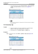
Page 127: ...5 6 3 Querying Logs Context Logs record operations on the system Maintenance and technical service engineers can query logs to locate operations on the system To query logs log in as the Admin Engineer or Operator user Procedure Step 1 On the home screen choose Maint Log Maint Query Logs Figure 5 28 is displayed Figure 5 28 Query logs screen End NetCol8000 A 050 100 In room Air Cooled Smart Coolin...

Page 128: ...c heater and humidifier is displayed Enter the Device Details screen and then enter the menu of a specific component All parameters for the component are displayed Procedure When viewing the component status through Status choose Common Functions Status or Running Status on the home screen The general component status screen is displayed Figure 5 30 shows the screen displayed after choosing Runnin...

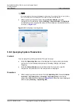
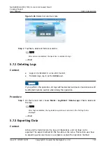
Page 129: ...eters through two ways Enter the Operating Info screen that displays the major system parameters such as the current detected temperature humidity voltage and power frequency Enter the Device Details screen and then enter the menu of a specific component All parameters for the component are displayed Procedure When querying system parameters through Operating Info choose Common Functions Operating...

Page 130: ... to view the compressor parameters as shown in Figure 5 33 Figure 5 33 Compressor parameters 5 6 7 Querying Version Details Procedure Step 1 On the home screen select About Figure 5 34 is displayed Figure 5 34 About screen NetCol8000 A 050 100 In room Air Cooled Smart Cooling Product User Manual 5 ACC Introduction Issue 12 2020 10 28 Copyright Huawei Technologies Co Ltd 121 ...

Page 131: ...ws the information of these T H boards When some T H boards of the cold or hot aisles are disabled T H Board on the About Version Info screen or T H Board on the About E label screen does not show the information of these T H boards End 5 7 Changing Parameters 5 7 1 Deleting Historical Alarms Context To delete historical alarms log in as the Admin user NOTICE Exercise caution when deleting all his...

Page 132: ...Procedure Step 1 On the home screen choose Maint Log Maint Delete Logs Yes to delete all the logs NOTE After logs are deleted the log deletion operation is recorded in the first log that is displayed End 5 7 3 Exporting Data Context Active alarms historical alarms logs configurations and run logs can be exported The export method for the five data is the same This section uses how to exporting act...

Page 133: ...s displayed at the status bar If the USB flash drive is not properly connected the system will notify that the USB flash drive is not detected Procedure Step 1 On the home screen choose Maint USB Operations Export Act Alarms to enter the Select Path screen as shown in Figure 5 37 Figure 5 37 Select path Step 2 Tap the file where the user saves active alarms in the Select Path dialog box and tap Ne...

Page 134: ...s displayed Tap OK Figure 5 40 Screen showing that data export has succeeded Step 4 Tap Maint USB Operations Remove USB to remove the USB flash drive in safe mode End NetCol8000 A 050 100 In room Air Cooled Smart Cooling Product User Manual 5 ACC Introduction Issue 12 2020 10 28 Copyright Huawei Technologies Co Ltd 125 ...

Page 135: ... 5 Calibrating a Sensor Context Calibrate a sensor if the displayed temperature or humidity on the sensor deviates from the actual value For example if the return air temperature measured by other temperature detection devices at the return air detection point is 20 C while the value measured by the sensor is 22 C the sensor has an error of 2 C and the calibration value should be set to 2 C To cal...

Page 136: ...he responding point is unfavorably big or the screen does not respond when being tapped To calibrate the touchscreen log in as the Admin or Engineer user NOTICE You can calibrate the screen by DIP switch only when the system enters Quick Settings page after the first power on or when the system is on the home screen Touch the LCD screen firmly if you are using your fingertips It is recommended tha...

Page 137: ...to ON and others remain unchanged the screen calibration function is triggered After 15 seconds a dialog box indicating Are you sure you want to calibrate the screen If you do not click Yes or No calibration will start automatically 10 seconds later is displayed as shown in Figure 5 45 Figure 5 45 Confirming to calibrate the screen NetCol8000 A 050 100 In room Air Cooled Smart Cooling Product User...

Page 138: ... If you need to perform quick settings in other scenarios log in as the Admin Engineer or Operator user Procedure Step 1 Choose Settings Quick Settings on the home screen The quick settings screen is displayed as shown by 1 2 3 and 4 in Figure 5 3 End 5 9 How to Set the Language Date or Time Context Enter the User Settings screen to set the Language Date format Date Time Time zone Password You can...

Page 139: ...home screen choose Settings User Settings to enter the User Settings screen as shown in Figure 5 47 Figure 5 47 User settings screen Step 2 Tap Password to enter the password changing screen as shown in Figure 5 48 NOTE It is recommended that the password should contain at least two types of characters NetCol8000 A 050 100 In room Air Cooled Smart Cooling Product User Manual 5 ACC Introduction Iss...

Page 140: ...ords of all users are restored to initial ones Other users may be affected Therefore exercise caution when performing password restoration To ensure device security operate the DIP switch after powering off the main power supply of the device Procedure Step 1 Disconnect the main power supply of the device Step 2 Set bits 1 and 3 of the DIP switch S2 to ON and other bits to non ON Figure 5 49 shows...

Page 141: ...ystem will display the following information and enter upgrade mode when the model cannot be identified or does not match or the software versions of the LCD and control board are incompatible The model cannot be identified Entering upgrade mode The model does not match Entering upgrade mode Failed to obtain the version information Entering upgrade mode The display board and control board software...

Page 142: ...ep 3 If the fault persists contact Huawei technical support End 5 13 How to Manually Clear Alarms Context This topic uses the Comp HP switch lock alarm as an example to describe how to manually clear alarms If you need to manually clear alarms log in as the Admin or Engineer user Procedure Step 1 On the home screen tap Alarms Query Act Alarms Comp HP lock The alarm information is displayed as show...

Page 143: ...me screen choose Settings System Settings T H Sensor Step 2 Set Cold aisle sensor 1 and Cold aisle sensor 2 to Enable as shown in Figure 5 51 Figure 5 51 Enabling a humidity and temperature sensor End 5 15 How to View Teamwork Control Information Procedure Step 1 On the home screen choose The teamwork control information is displayed as shown in Figure 5 52 NetCol8000 A 050 100 In room Air Cooled ...

Page 144: ...fter Default Settings Are Operated After choosing Settings Restore Defaults Yes the following parameters are displayed All parameters displayed on Settings System Settings All parameters displayed on Settings Alarm Settings All parameters displayed on Settings Comm Settings Date format and time zone settings displayed on Settings User Settings All parameters displayed on Maint Sensor Adjust NOTICE...

Page 145: ... faults are beyond the warranty scope Remember the new password NOTE When Windows accesses the controller over SSH you need to use client software such as PuTTY Procedure Step 1 Log in to the controller over SSH Step 2 Specify User name and Password The preset user name and password are enspire and Changeme respectively as shown in Figure 5 53 Figure 5 53 Entering the user name and password NetCol...

Page 146: ...rds for five times the user s account will be locked for 10 minutes Step 3 After successful login enter su and Changeme to switch to the root user as shown in Figure 5 54 Figure 5 54 Switching to the root user Step 4 Enter passwd the password change command to change the password In the displayed window enter a new password and confirm it as shown in Figure 5 55 NetCol8000 A 050 100 In room Air Co...

Page 147: ...the E label identification board is abnormal or the E label identification board is not properly connected an exception may occur during E label identification If the information shown in Figure 5 56 is displayed on the controller LCD the smart cooling product can run properly To remove this tip perform Step 1 Figure 5 56 Message 1 NetCol8000 A 050 100 In room Air Cooled Smart Cooling Product User...

Page 148: ...oduct Step 3 Check whether the E label identification board is properly connected If no reconnect the board properly and continue with Step 5 If yes continue with Step 4 Step 4 Check whether cables are properly connected If yes contact Huawei technical support to replace the E label identification board If no reconnect or replace cables and perform Step 5 Step 5 Reconnect the main power supply of ...

Page 149: ...int USB Operations Import Certificate as shown in Figure 5 58 Figure 5 58 Importing a certificate NOTE The screenshot is for reference only The actual UI display prevails Step 2 Tap Browse next to Upload CA certificate file Step 3 Select CA certificate file to be imported Step 4 Upload local certificate file and key file in turn in the same way Step 5 Enter Key password and Confirm key password St...

Page 150: ...value before is the setting before change and the value after is the setting after change NOTE The log query screen displays logs of LCD user operations including user login and setting change records Figure 6 1 Query Logs NetCol8000 A 050 100 In room Air Cooled Smart Cooling Product User Manual 6 FAQ Issue 12 2020 10 28 Copyright Huawei Technologies Co Ltd 141 ...

Page 151: ...cument do not represent all safety instructions They are only supplements to the safety instructions Personnel who will install operate and maintain Huawei equipment must receive thorough training understand all necessary safety precautions and be able to correctly perform all operations Pay attention to the safety symbols on the equipment and all safety instructions in this document The safety pr...

Page 152: ...ponent replacement do not lean any material against the cabinet 7 1 2 Filters Table 7 1 Filters No Operations Troubleshooting Remarks 1 Verify that the air filters are clean and not blocked If an air filter is dirty and blocked clean it using a vacuum cleaner shake dust off it or replace it Perform the operations with the power off 2 Check whether the air filter is damaged or deformed Replace the ...

Page 153: ...e pressure tube of the air filter clogging switch is fixed properly The pressure tube is fixed under the air filter and it is on the right side of the unit If the fault is not rectified contact Huawei technical support to replace the air filter clogging switch Perform the operations with the power on 7 1 3 Indoor Fans Table 7 2 Indoor fan monthly maintenance item No Operations Troubleshooting Rema...

Page 154: ...wer off 7 1 4 Compressors Table 7 3 Compressor monthly maintenance item No Operations Troubleshooting Remarks 1 Check the four compressor fixing screws are firm Tighten the screws Perform the operations with the power off 2 Check that the angle valves on the compressors have no oil stain Clean no oil stain Perform the operations with the power off 3 Check that the oil sight glass has no many air b...

Page 155: ...nts of the humidifier contact QC3 for a NetCol8000 A050 unit and QC9 for a NetCol8000 A100 unit in turn using a clamp meter Verify that the phase currents exist and differ by less than 20 The normal current range for a NetCol8000 A050 infrared humidifier is 7 5 9 A and that for a NetCol8000 A100 infrared dehumidifier is 12 13 5 A Replace it by referring to 7 4 4 Replacing the Infrared Humidifier L...

Page 156: ...es for dry heating protection 4 Refer to 7 4 4 Replacing the Infrared Humidifier Lamps to remove and clean the water pan 5 Fix the filter port using a wrench as shown by 1 in Figure 7 3 remove the filter using the wrench as shown by 2 in Figure 7 3 and clean the Y shaped strainer using a brush 6 Clean up dirt in the water pan with a hard brush and detergent and wash the water pan with water 7 Inst...

Page 157: ... Self drainpipe Figure 7 2 NetCol8000 A100 infrared humidifier structure 1 Ceramic lamp holder 2 Water pan 3 Self drainpipe 4 Manual reset temperature switch for dry heating protection 5 Automatic reset temperature switch for dry heating protection 6 Water inlet 7 Infrared humidifier lamp 8 Topside overheat temperature switch 9 High water level detection switch NetCol8000 A 050 100 In room Air Coo...

Page 158: ...current deviation does not exceed 20 Replace the electric heater by referring to 7 4 5 Replacing Electrical Heaters Perform the operations with the power on 2 Check that no foreign matter exists on the electric heater surface Clean the foreign matters Perform the operations with the power off 3 Check for corrosion on the heater surface You can remove the rust using a metal brush Replace the heater...

Page 159: ...pressor The following table lists the reasonable discharge pressure ranges Table 7 6 Reasonable discharge pressure ranges Ambient Temperature Discharge Pressure Range 15 C or lower 1 9 MPa to 2 5 MPa 15 C 35 C 2 1 MPa to 3 1 MPa 35 C 55 C 2 65 MPa to 4 2 MPa Suction Pressure When suction pressure is below the low pressure switch threshold the switch reacts to stop the compressor Excessive suction ...

Page 160: ...ecommended that you do not adjust the thermostatic expansion valve onsite because it has been adjusted before delivery If the superheat degree is too low or high adjust the thermostatic expansion value as follows at your deliberation or after consulting Huawei technical support 1 Unscrew the valve bonnet at the bottom 2 Rotate the adjustment screw rod clockwise to increase the superheat degree 3 R...

Page 161: ...ty sensor Connect the cables again Perform the operations with the power off 4 Check that the main control board is properly connected to each contactor electric heater temperature switch dry heating protection temperature switch of the infrared humidifier water pan filter clogging switch and fan airflow loss switch Connect the cables again Perform the operations with the power off 5 Use a brush o...

Page 162: ... sensor a optional is securely installed and its probe is appropriately located Figure 7 4 shows the recommended positions for installing Water sensors Locate it to the appropriate position Perform the operations with the power off a A Water sensor monitors resistance changes at terminals to check whether the floor is watery The resistance at the terminals becomes small if the terminals detect wat...

Page 163: ...ng Water sensors 1 Indoor unit 2 Water sensors 3 Floor drainpipe NetCol8000 A 050 100 In room Air Cooled Smart Cooling Product User Manual 7 System Operation and Maintenance Issue 12 2020 10 28 Copyright Huawei Technologies Co Ltd 154 ...

Page 164: ...the temperatu re and humidity collection board fails to communic ate when the alarm detection delay expires 1 Dirt or water exists around the T H sensor which leads to a detection fault 2 The T H sensor is faulty 1 Remove dirt or water from the T H sensor 2 Maintain or replace the T H sensor NetCol8000 A 050 100 In room Air Cooled Smart Cooling Product User Manual 7 System Operation and Maintenanc...

Page 165: ...t 2 The return air temp is higher than the return air HT alarm thres during startup 3 The ambient temp is high 4 The return air HT alarm thres is inappropriate 5 The temp displayed is different from the actual temp 1 Add more smart cooling product units 2 Check other causes if the alarm persists after startup 3 Check the ambient temp 4 Adjust the return air HT alarm thres 5 Calibrate or replace th...

Page 166: ...tion delay expires 1 The load is low 2 The ambient temperature is low 3 The return air LT alarm thres is inappropriate 4 The temp displayed is different from the actual temp 1 Please consult Huawei technical support 2 Check the ambient temperature 3 Adjust the return air LT alarm thres 4 Calibrate or replace the abnormal temp sensors For details about how to calibrate the sensor see 5 7 5 Calibrat...

Page 167: ... a007 T H board comm failed Critic al The main control board fails to communic ate with the temperatu re and humidity collection board when the alarm detection delay expires 1 The cables to the T H sensor are loose or damaged 2 The DIP switch of the T H sensor is set incorrectly 3 The T H sensor is faulty 4 The communication port of the control board is faulty 1 Check the cables to the T H sensor ...

Page 168: ...e or damaged 6 The high press switch is faulty 7 The solenoid valve is faulty 8 The refrigerant is overfilled 1 Check the power supply of the outdoor unit 2 Check the on off signal cables of the outdoor unit 3 Clean the condenser fins 4 Maintain or replace the outdoor unit or unit driver 5 Check the cables to the high press switch 6 Maintain or replace the high press switch 7 Maintain or replace t...

Page 169: ... within one consecutiv e hour or a compresso r high pressure alarm is not cleared within 10 minutes The a008 comp HP alarm is generated frequently Reference to the solutions for the a008 comp HP alarm NetCol8000 A 050 100 In room Air Cooled Smart Cooling Product User Manual 7 System Operation and Maintenance Issue 12 2020 10 28 Copyright Huawei Technologies Co Ltd 160 ...

Page 170: ...ked 6 The expansion valve is blocked 7 The indoor fans are faulty 1 Check for any leakages Fill refrigerant after maintenance or replacement 2 Maintain or replace the solenoid coil or solenoid valve 3 Check cables to the low pressure switch 4 Maintain or replace the low pressure switch 5 Maintain or replace the dryer filter 6 Maintain or replace the expansion valve 7 Maintain or replace the indoor...

Page 171: ... s within one consecutiv e hour or a compresso r low pressure alarm has not cleared within 30 minutes The a010 comp LP alarm is generated frequently Reference to the solutions for the a010 comp LP alarm NetCol8000 A 050 100 In room Air Cooled Smart Cooling Product User Manual 7 System Operation and Maintenance Issue 12 2020 10 28 Copyright Huawei Technologies Co Ltd 162 ...

Page 172: ...ischarge temperature switch is faulty 5 Outdoor fans are faulty 6 The condenser fins are blocked 1 Check for any leakages Fill refrigerant after maintenance or replacement 2 Clean the condenser fins 3 Check the ambient temperature 4 Check cables to the discharge temperature switch 5 Maintain or replace the discharge temperature switch 6 Maintain or replace the outdoor units NetCol8000 A 050 100 In...

Page 173: ...a012 comp discharge HT alarm a014 Comp short period Warni ng A compresso r has been switched off and on 10 times during the monitored period and each running period is less than 1 5 times of the shortest configure d running period 1 The comp starts and stops frequently affected by other alarms 2 The load is low which leads to the comp starting and stopping frequently 1 Clear other alarms 2 Please ...

Page 174: ...rential pressure switch is blocked or cracked or is secured in an inappropriate position 3 Cables to the differential pressure switch are loose or damaged 4 Indoor fans are faulty 1 Adjust the threshold for the differential pressure switch 2 Maintain or replace the differential pressure tube 3 Check cables to the differential pressure switch 4 Maintain or replace the fans a018 Indoor fan exceed ru...

Page 175: ...tion switch 4 Maintain or replace the high water level detection switch a020 Humid ifier pan no water Major The dry heating protection temperatu re switch for the infrared humidifier water pan is triggered and the filter clogging switch is closed and does not recover for N s 1 The humidifier water pan has insufficient water 2 The manual reset temperature switch has not been reset 3 Cables to the h...

Page 176: ...a023 Elec heater HT Major The electric heater overtemp erature switch is triggered and the airflow loss differentia l pressure switch is closed and does not recover for N s 1 Temperature switch probes are located inappropriately 2 The cables to the temp switch of the electric reheat are loose or damaged 3 The temperature switch is faulty 4 The manual reset temperature switch is not reset 5 The ind...

Page 177: ...xpires 1 Air filters are blocked 2 The differential pressure switch is faulty 3 The air filter differential pressure switch is inappropriately set 4 The differential pressure switch is inappropriately located or blocked 5 Cables to the differential pressure switch are loose or damaged 1 Maintain or replace the air filters 2 Replace the differential pressure switch 3 Adjust the threshold for the di...

Page 178: ...reshold Maintain or replace the air filter and clear the accumulated runtime a027 Power loss Warni ng The power supply is lost during normal operation When a restart is initiated the main control board checks the NetCol800 0 A state If a cold reset is required this alarm is generated If a hot reset is required this alarm is not generated The supply power is cut off Check the power supply cables Ne...

Page 179: ... is higher than the power overvolt alarm thres 2 If a voltage jumper is used possibly it is incorrectly connected 3 If a toggle switch is used possibly it is incorrectly set 1 Check the power supply voltage 2 Maintain or replace the voltage jumper 3 Correctly set the toggle switch a030 Power phase C overvo lt Major The AC voltage of phase C is greater than the alarm threshold and the alarm detecti...

Page 180: ...eplace the voltage jumper 3 Correctly set the toggle switch a032 Power phase B underv olt Major The AC voltage of phase B is greater than 50 V and less than the low voltage alarm threshold when the alarm detection delay expires 1 The power supply voltage is lower than the power overvolt alarm thres 2 If a voltage jumper is used possibly it is incorrectly connected 3 If a toggle switch is used poss...

Page 181: ...e switch a034 Power overfre q Major The AC frequency is greater than the high frequency alarm threshold when the alarm detection delay expires 1 The power grid is unstable 2 The surge protection and filtering board is faulty 1 Check the power grid 2 Replace the surge protection and filtering board a035 Power underf req Major The AC frequency is less than the low frequency alarm threshold when the ...

Page 182: ...tection and filtering board detects an incorrect angle among three phases when the alarm detection delay expires 1 The power grid is unstable 2 The surge protection board is faulty 1 Check the power grid 2 Maintain or replace the surge protection board a042 Remot e shutdo wn Critic al The remote power off switch polarity is different from the preset polarity 1 The remote shutdown dry contact is tr...

Page 183: ...5 Teamw ork mode failed Major The local unit cannot obtain teamwork parameter s from the master unit even though teamwork control is configure d for the local unit or the master and a slave unit have the same address 1 The DIP switch is set incorrectly for teamwork 2 The teamwork cables are loose or damaged 3 Any two smart cooling product units have the same address 4 No smart cooling product unit...

Page 184: ...ter maintenance or replacement 2 Maintain or replace the solenoid coil or the solenoid valve 3 Check the cables to the low press sensor 4 Maintain or replace the low press sensor 5 Maintain or replace the filter dryer 6 Maintain or replace the expansion valve a083 Surge protect ion board fault Critic al N A 1 The SPD is faulty 2 The cables to the SPD are loose or damaged 3 The port of the control ...

Page 185: ...ction delay expires 1 A device on loop A is faulty 2 The loop A fuse is loose aged or disconnected 1 Maintain or replace the faulty device on loop A 2 Maintain or replace the fuse a086 Route B fuse discon nect Critic al The compresso r control loop fuse reports that the switch polarity is different from the preset polarity when the alarm detection delay expires 1 A device on loop B is faulty 2 The...

Page 186: ...e the faulty device on loop C 2 Maintain or replace the fuse a088 Route D fuse discon nect Major Any other control loop fuse reports that the switch polarity is different from the preset polarity when the alarm detection delay expires 1 A device on loop D is faulty 2 The loop D fuse is loose aged or disconnected 1 Maintain or replace the faulty device on loop D 2 Maintain or replace the fuse NetCo...

Page 187: ...midity 4 Adjust the high humidity alarm thres 5 Calibrate or replace the abnormal T H sensors a094 Low humidi ty Warni ng The return air humidity reading is valid and lower than the low humidity alarm threshold when the alarm detection delay expires 90s after a fan startup signal is sent 1 The T H sensors are located in inappropriate position 2 The ambient humidity is low 3 The low humidity alarm ...

Page 188: ...essional technicians are allowed to perform maintenance Exercise caution during live line troubleshooting If jumpers are used for troubleshooting remove them after troubleshooting Connected jumpers may affect control functions and damage equipment Table 7 9 NetCol8000 A troubleshooting Symptom Possible Cause Reference Solution The NetCol8000 A generates abnormal voice Compressor fans or pipes are ...

Page 189: ...o not expose them to direct sunshine and verify that the distances meet requirements in the installation manual Check whether the air exhaust pressure is too high If the air exhaust pressure is too high re inject refrigerant to expel free air from the cooling loop Heat dissipation is poor because the condenser is dirty or blocked Clean the condenser fins The outdoor fan fails Check whether the out...

Page 190: ...sufficient Add the lubricant The transport sheet metal is not removed from a compressor Remove the sheet metal The compressor suction temperature is too high Suction temperature is higher than 25 C Adjust the thermostatic expansion valve or add refrigerant An indoor fan fails to start Either the main circuit breaker or the indoor fan circuit breaker is not switched on Check the circuit breaker sta...

Page 191: ...umidifier is not filled with water Check whether the water pressure is proper Check the status of the water injection solenoid valve Check whether the water injection pipe is blocked Check whether the water inlet pipe valve is opened There is no humidification requirement Check for any requirement on the LCD The heating function fails The electrical heater temperature switch is being protected Vie...

Page 192: ...sistance properties with an ohmmeter 7 4 Parts Replacement After replacing any part verify that the new part works properly 7 4 1 Replacing the Filters Context Figure 7 5 shows the positions of filters in the indoor unit They are numbered 1 and 2 Figure 7 5 Filter positions NetCol8000 A 050 100 In room Air Cooled Smart Cooling Product User Manual 7 System Operation and Maintenance Issue 12 2020 10...

Page 193: ...ng process Exercise caution during the lowering process to prevent personal injuries because the indoor fan is heavy Context Recommended tools small sized flat head screwdriver 5 x 200 mm flat head screwdriver adjustable wrench diagonal pliers and Phillips screwdriver Procedure Step 1 Disconnect the power supply Step 2 Cut off the cable ties on the corrugated pipe of the fan power cable using the ...

Page 194: ...e floor of the connecting screw around four Slowly rotate the handle of the capstan to hoist the indoor fan above the bottom plate Step 8 Drag the indoor fan outwards and pay out more steel wire until the fan tooling beam approaches to the compressor beam Step 9 Lift the indoor fan and remove the fan tooling beam Step 10 Drag the indoor fan out of the unit Figure 7 7 Replacing an indoor fan NetCol...

Page 195: ... upside down with caution Figure 7 8 Removing the fan cover Step 12 Remove the four screws on the motor control box at the bottom of the fan using a 5x200 mm flat head screwdriver NetCol8000 A 050 100 In room Air Cooled Smart Cooling Product User Manual 7 System Operation and Maintenance Issue 12 2020 10 28 Copyright Huawei Technologies Co Ltd 186 ...

Page 196: ...e the screw PE cable in the area marked yellow in using a 5 x 200 mm flat head screwdriver Figure 7 10 Motor control box Step 14 Remove the eight screws securing the fan to the bottom plate using an adjustable wrench pull up the fan cover and take out the fan NetCol8000 A 050 100 In room Air Cooled Smart Cooling Product User Manual 7 System Operation and Maintenance Issue 12 2020 10 28 Copyright H...

Page 197: ...n total runtime End 7 4 3 Replacing a Compressor Prerequisites Required tools two adjustable wrenches a torque wrench a welding torque a nitrogen cylinder to be prepared onsite LOCTITE 554 glue optional a new compressor and a new dryer filter Context DANGER When replacing a compressor avoid skin contact with the refrigerant or lubricant to prevent frostbite or burns NetCol8000 A 050 100 In room Ai...

Page 198: ...urn the angle valve nut shown by 2 in Figure 7 12 counterclockwise using a torque wrench Remove the suction and discharge angle valves Seal the air intake and exhaust vents to ensure that the system is clean and moisture does not enter the pipes Figure 7 12 Removing the air intake and exhaust angle valves Step 5 Loosen the bolts and take out the compressor Step 6 Blow away dirt with nitrogen check...

Page 199: ... new dry filter in reverse order And solder new the dry filter to the original position on the pipe Step 7 Install a new compressor vacuumize the system and partially inject refrigerant NetCol8000 A 050 100 In room Air Cooled Smart Cooling Product User Manual 7 System Operation and Maintenance Issue 12 2020 10 28 Copyright Huawei Technologies Co Ltd 190 ...

Page 200: ...ature of the water in the pan is close to the room temperature which avoids causing scalds NOTE A highly clean lamp surface is required for the infrared humidifier Direct touches are not allowed for they will shorten the humidifier service life Wear clean cotton gloves when dealing with the lamp Refill water after the lamp is changed Otherwise the infrared humidifier may act abnormally The followi...

Page 201: ... float sheet metal using a Phillips screwdriver and take out the float and sheet metal Figure 7 17 Removing the float sheet metal Step 5 Remove the four wiring terminals connecting the manual and automatic reset switches at the bottom of the water pan using combination pliers NetCol8000 A 050 100 In room Air Cooled Smart Cooling Product User Manual 7 System Operation and Maintenance Issue 12 2020 ...

Page 202: ... metal 2 Remove the two screws that secure the sheet metal 3 Loosen the bolts of the damaged lamp tube from the ceramic terminal block by using hex key while holding the ends of the lamp tube with hands Step 7 Take out the lamp tube and install a new one NetCol8000 A 050 100 In room Air Cooled Smart Cooling Product User Manual 7 System Operation and Maintenance Issue 12 2020 10 28 Copyright Huawei...

Page 203: ...the water inlet for the infrared humidifier Step 2 Remove the four wiring terminals connecting the manual and automatic reset switches at the bottom of the water pan using combination pliers as shown in Figure 7 18 Step 3 Pull out the self overflow vent and drain the water from the water pan After the water is drained remove the drainpipe remove the two screws on the right of the infrared humidifi...

Page 204: ...ep 7 Step 9 Power on the unit and tap Maint Diagnostic Mode Enter open the solenoid valve and the humidifier Make sure they work properly Exit the Diagnostic Mode Step 10 Tap Maint Performance Maint to clear the humidifier total runtime End Replacing a Water Supply Valve Recommended tools and materials for replacing a water supply valve a Phillips screwdriver an adjustable wrench and a new water s...

Page 205: ...justable wrench Then remove the water injection solenoid valve NOTICE Keep the connection nuts aside for reinstallation purpose Apply yellow glue to the nut of the water inlet pipe and install the solenoid valve NetCol8000 A 050 100 In room Air Cooled Smart Cooling Product User Manual 7 System Operation and Maintenance Issue 12 2020 10 28 Copyright Huawei Technologies Co Ltd 196 ...

Page 206: ...ICE Prevent bolts from falling into the fan when you loosen the bolts on the electrical heater rack Hold the electrical heater rack with hands while moving it to prevent the rack from falling to the bottom of the NetCol8000 A when the rack is out of position The electrical heater rack is inside the NetCol8000 A Exercise caution during maintenance to prevent internal components from scratches or da...

Page 207: ...the unit and tap Maint Diagnostic Mode Enter to open the electric heater Make sure they work properly Exit the Diagnostic Mode Step 6 Tap Maint Performance Maint to clear the electric heater total runtime Figure 7 24 Replacing an electrical heater bottom view 1 Temperature switch 2 Electrical heater End NetCol8000 A 050 100 In room Air Cooled Smart Cooling Product User Manual 7 System Operation an...

Page 208: ...he holes which routing cables and the pipes please cut out holes to avoid interfering c When the width of angle steel is more than 79 5 mm it is interfering with the holes which lowering fans please cut out holes to avoid interfering 3 It s width between support and cabinet fixing bolt hole is 55 mm weld the bolts on the L shape or other parts and then weld them on the support when it is unable to...

Page 209: ...Col8000 A050 unit mm Figure A 2 Support specifications of NetCol8000 A100 unit mm NetCol8000 A 050 100 In room Air Cooled Smart Cooling Product User Manual A Support Specifications Issue 12 2020 10 28 Copyright Huawei Technologies Co Ltd 200 ...

Page 210: ...n control board for the indoor unit 10 Temperature and humidity collection board 11 Compressor contactor QC1 12 Electrical heater contactor QC2 13 Humidifier contactor QC3 14 Fan power supply contactor QC4 15 Transformer TC 16 Electronic label 17 Voltage jumper 18 Control terminals 19 Surge protection and filtering board Filter 20 General power circuit breaker QS 21 Ground bar PE Figure B 2 shows ...

Page 211: ...the indoor unit 15 Filter clogging protection switch 16 Airflow loss switch 1 17 Airflow loss switch 2 18 Temperature and humidity collection board 19 Compressor 1 contactor QC1 20 Compressor 2 contactor QC2 21 Electrical heater 1 contactor QC7 22 Electrical heater 2 contactor QC8 23 Humidifier contactor QC9 24 Fan 1 power supply contactor QC10 25 Fan 2 power supply contactor QC11 26 Control termi...

Page 212: ... Commutation G GPRS General Packet Radio Service L LCD Liquid Crystal Display LUI LCD User Interface T TFT Thin Film Transistor P PTC Positive Temperature Coefficient NetCol8000 A 050 100 In room Air Cooled Smart Cooling Product User Manual C Acronyms and Abbreviations Issue 12 2020 10 28 Copyright Huawei Technologies Co Ltd 203 ...

Page 213: ...Col8000 A050 Figure D 1 Electrical Schematic Diagram NetCol8000 A 050 100 In room Air Cooled Smart Cooling Product User Manual D Electrical Schematic Diagram NetCol8000 A050 Issue 12 2020 10 28 Copyright Huawei Technologies Co Ltd 204 ...

Page 214: ...Col8000 A100 Figure E 1 Electrical Schematic Diagram NetCol8000 A 050 100 In room Air Cooled Smart Cooling Product User Manual E Electrical Schematic Diagram NetCol8000 A100 Issue 12 2020 10 28 Copyright Huawei Technologies Co Ltd 205 ...

Page 215: ...Menu Structure Figure F 1 Controller Menu Structure NetCol8000 A 050 100 In room Air Cooled Smart Cooling Product User Manual F Controller Menu Structure Issue 12 2020 10 28 Copyright Huawei Technologies Co Ltd 206 ...

Reviews: