background image

16

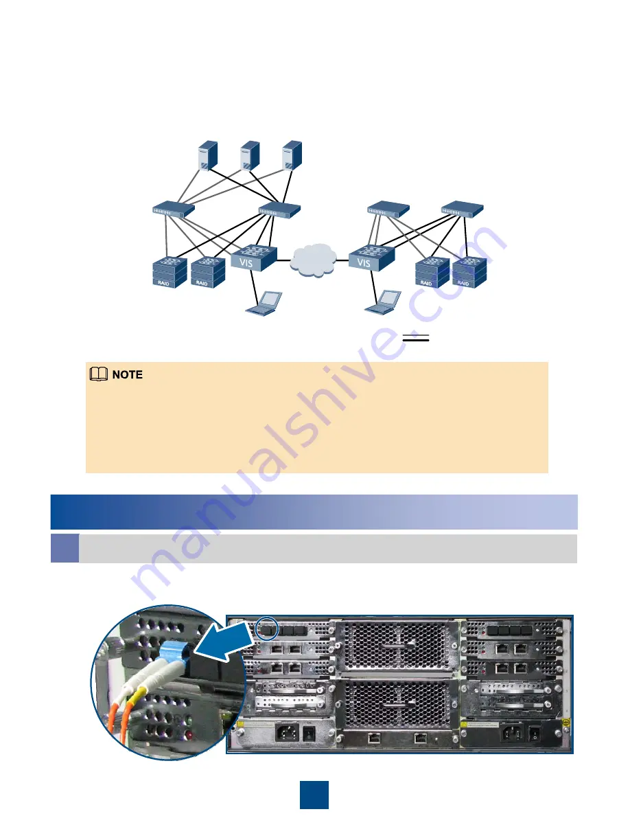
Scenario 2: Networking for Connection of the Production 
Center and the Disaster Recovery Center (Only the Ethernet 
Switch Is Used in the Networking of the Production Center and 
the Disaster Recovery Center)

The connection of port modules on the left and right of the rear of the VIS6000 is symmetrical. The 
following operation takes port modules on the left of the rear of the VIS6000 as an example. For the 
connection of port modules on the right, see the following installation procedure to perform similar 
operations.
The signal cables are wired on the right of the rear of the cabinet (you can lead signal cables connected 
to the left port modules to the right of the cabinet by using the cable tray). When cabinets are connected, 
wire the connecting cables inside the cabinet support bridges.
For the FC service ports to which FC cables are not connected, use protective caps.

Scenario 1: Connecting One End of the Optical Fiber to the FC Service Port of the 
VIS6000

2 Connecting the VIS6000 to the Switch

a

Connect One End of the Cable to the Service Port of the VIS6000

Linux

AIX

Windows

VIS6000

VIS6000

WAN

Network cable

Storage arrays

Maintenance terminal

Ethernet 

switch

Ethernet switch

Storage arrays

Maintenance terminal

Ethernet switch

Ethernet switch

Summary of Contents for OceanStor VIS6300

Page 1: ...HUAWEI TECHNOLOGIES Co Ltd OceanStor VIS6000 Series Virtual Intelligent Storage System V100R001 Quick Installation Guide Issue 03 Part Number 3150G070 Date 2010 05 10 ...

Page 2: ...Installing the VIS6000 in the Cabinet 8 Connecting Grounding Cable 13 Connecting Storage Array and Application Server to the VIS6000 14 Connecting the Production Center to the Disaster Recovery Center 25 Connecting the VIS6000 to the Maintenance Terminal 28 Connecting Power Cable 33 Power on 35 Appendixes 38 ...

Page 3: ... VIS6600 is superior to the VIS6300 in hardware configuration and has more powerful capability of processing services Unless otherwise specified this document takes the VIS6000 with the AC power as an example This document takes the VIS6000 that is installed to the N610E 22 cabinet as an example This document is based on the prerequisite that the N610E 22 cabinet is well installed and grounded Res...

Page 4: ...ial list includes grounding cables and power cables Material List 1 Tools Cross screwdriver Flathead screwdriver Cutter Captive nut mount bar Antistatic gloves Antistatic clothes Cable tie Fiber binding strap The plugged ESD preventive wrist strap for the grounding terminal ...

Page 5: ...to fill in related information 2 Cables Network cable Serial port cable converting RJ 45 to DB 9 Optical fiber 3 Other Devices FC switch take the Brocade 200E fiber channel switch as an example Ethernet switch take the HUAWEI Quidway S5600 series as an example Application server take DELL PowerEdge 2950 as an example Maintenance terminal ...

Page 6: ...d in slot 0 1 or 2 According to the actual application environment choose the types and numbers of port modules If the interface card does not carry port modules use a filler panel to hide the interface card The controller A and B must carry port modules in the same mode The sequence of port modules on each side in the VIS6000 must be consistent In this way the 1 1 redundant backup can be achieved...

Page 7: ...E service port System disk Hot swap control button a a The hot swap control buttons on the GE port module and the FC port module are reserved The current version does not support the use of the button Do not perform any operation on the button otherwise system services might be disrupted b The management port module provides two management network ports and one mute alarm button The left network p...

Page 8: ...rocedure Start Take antistatic measures Install the VIS6000 in the cabinet Install the VIS6000 in the cabinet Connect the grounding cable Connect the storage array and application server to the VIS6000 Connect the production center to the disaster recovery center Connect the VIS6000 to the maintenance terminal Connect power cable Power on the devices End ...

Page 9: ...entive wrist strap with metallic clip you can clip the ESD preventive wrist strap with metallic clip to the cabinet directly 1 Wearing an Antistatic Wrist Strap 2 Wearing Antistatic Clothes 3 Wearing Antistatic Gloves Scenario 1 Wearing an Antistatic Wrist Strap Plugged Scenario 2 Wearing an Antistatic Wrist Strap With Metallic Clip Taking Antistatic Measures ...

Page 10: ...0 at the bottom of the cabinet for the convenience of ventilation and heat dissipation of VIS6000 components 1 Specifying the Position of the VIS6000 in the Cabinet a Locate the VIS6000 Installing the VIS6000 in the Cabinet Filler panel 2U AC power distribution box 3U VIS6000 4U Filler panel 1U Other devices 1U Cabling subrack 1U Storage devices 4U Storage devices 4U Storage devices 4U Storage dev...

Page 11: ...osen the Screws on the Filler Panels Using a Cross Screwdriver Remove the Filler Panels a Specify the Installation Positions of Guide Rail by Using the Installation Template 2 Locating and Installing Guide Rail ...

Page 12: ...the figure Ensure that the direction of the adjustable guide rail is right Align the positioning pins of the guide rail with the mounting holes of the slide rail on the inner side of the cabinet see step Fix the adjustable guide rail on the slide rail of the cabinet with screws On the front side of the slide rail the screw is installed in the third hole of the adjustable guide rail On the rear sid...

Page 13: ...ake it Stuck to the Pane of the Square Hole 2 Insert the Other Foot of the Captive Nut into the Square Hole and Make it Stuck to the Pane of the Square Hole with a Captive Nut Mount Bar 3 Status After Installation 4 Fixing the VIS6000 to the Cabinet If the VIS6000 is fully configured arrange more than three persons to carry them and take cares to avoid injury to any person Carry the VIS600 by usin...

Page 14: ...13 a Installing Fixed Bolt to the System Subrack c Fix the VIS6000 in the Cabinet b Push the VIS6000 into the Cabinet ...

Page 15: ...he material list of the VIS6000 to the cabinet Before connecting the grounding cable to the cabinet grounding end check whether the cabinet grounding end is covered by insulation paint If the cabinet grounding end is covered by insulation paint scrape the paint off and then connect the grounding cable to the cabinet grounding end If the grounding end is not covered by insulation paint connect the ...

Page 16: ...tual environment This section takes the networking mode that uses only the FC switch or the Ethernet switch in the production center or the disaster recovery center as an example You can the choose FC network within 60 KM or Ethernet to connect the production center to the disaster recovery center Please choose the networking mode according to the actual environment The following figures take the ...

Page 17: ...al cables are wired on the right of the rear of the cabinet you can lead signal cables connected to the left port modules to the right of the cabinet by using the cable tray When cabinets are connected wire the connecting cables inside the cabinet support bridges For the FC service ports to which FC cables are not connected use protective caps Scenario 1 Connecting One End of the Optical Fiber to ...

Page 18: ...k Cable to the GE Service Port of the VIS6000 Scenario 1 Laying Optical Fibers b Laying Cables The figures take the wiring inside the cabinet as an example For the wiring outside the cabinet overhead wiring and underfloor wiring see the appendixes ...

Page 19: ...18 Scenario 2 Laying Network Cables Scenario 1 Connecting the Other End of the Optical Fiber to the Port of the FC Switch C Connect the Other End of the Cable to the Switch ...

Page 20: ...to the FC Host Port The following section takes the OceanStor S5600 with FC and iSCSI host ports hereinafter referred to as the S5600 as an example Scenario 2 Connecting One End of the Network Cable to the iSCSI Host Port 3 Connecting the Storage Array to the Switch a Connect One End of the Cable to the Front end Host Port of the Storage Array ...

Page 21: ...0 Scenario 1 Laying Optical Fibers The figures take the wiring inside the cabinet as an example For the wiring outside the cabinet overhead wiring and underfloor wiring see the appendixes b Laying Cables ...

Page 22: ...21 Scenario 2 Laying Network Cables ...

Page 23: ... of the Network Cable to the Port of the Ethernet Switch Scenario 1 Connecting One End of the Optical Fiber to the FC HBA Port of the Application Server c Connect the Other End of the Cable to the Switch 4 Connecting the Application Server to the Switch a Connect One End of the Cable to the Port of the Application Server ...

Page 24: ...ke the wiring inside the cabinet as an example For the wiring outside the cabinet overhead wiring and underfloor wiring see the appendixes b Laying Cables Scenario 2 Connecting One End of the Network Cable to the Network Port of the Application Server ...

Page 25: ...24 Scenario 2 Laying Network Cables Scenario 1 Connecting the Other End of the Optical Fiber to the Port of the FC Switch c Connect the Other End of the Cable to the Switch ...

Page 26: ...25 Scenario 2 Connect the Other End of the Network Cable to the Port of the Ethernet Switch ...

Page 27: ...lease choose the networking mode according to the actual environment The following figure takes the Ethernet on which the production center and the disaster recovery center are connected WAN Controller A Controller B VIS6000 configured with GE port modules Controller B Controller A VIS6000 configured with GE port modules VIS6000 in the production center VIS6000 in the disaster recovery center Netw...

Page 28: ...Ethernet Switch a Connect One End of the Cable to the GE Service Port of the VIS6000 b Laying Network Cables This figure takes the wiring inside the cabinet as an example For the wiring outside the cabinet overhead wiring and underfloor wiring see the appendixes ...

Page 29: ... 3 Connecting the VIS6000 in the Disaster Recovery Center to the Ethernet Switch For details about connecting the VIS6000 in the disaster recovery center to the Ethernet switch see the operations about how to connect the VIS6000 in the production center to the Ethernet switch ...

Page 30: ...Debugging Serial Port Connecting the VIS6000 to the Maintenance Terminal The IP addresses of GE service ports management network ports configuration ports and heartbeat network ports of controllers cannot be configured in the same network segment The IP addresses of the heartbeat ports on controllers are in the 192 168 1 0 24 and 192 168 2 0 24 network segments and cannot be modified The IP addres...

Page 31: ...the Other End of the Network Cable to the Network Port of the Maintenance Terminal b b Connect the Other End of the Cable to the Network Port or the Serial Port of the Maintenance Terminal 2 Connecting the Management Network Port to the Ethernet Switch or the Maintenance Terminal a Connect One End of the Network Cable to the Management Port of the VIS6000 ...

Page 32: ...ork Port to the Maintenance Terminal The management network port module on the VIS6000 has two management network ports one on the left and the other on the right This section takes the left management network port in the rear of the VIS6000 as an example The process to connect the management network port on the right is similar b Laying Network Cables Perform the operation of the scenario corresp...

Page 33: ...h or the Network port of the Maintenance Terminal 3 Connecting the Maintenance Terminal to the Switch If the maintenance terminal is connected to the configuration network port of the VIS6000 it cannot provide a network port to connect the management network port In this case perform this operation after setting the IP addresses of the management network ports of controller A and controller B and ...

Page 34: ...etwork Cables a Connect One End of the Network Cable to the Port of the Ethernet Switch If the maintenance terminal is connected to the configuration network port of the VIS6000 it cannot provide a network port to connect the management network port In this case perform this operation after setting the IP addresses of the management network ports of controller A and controller B and disconnecting ...

Page 35: ...Connecting Power Cable AC Power 2 Plugging the AC Power Cable into the Power Socket and Fixing the Connector to the Power Socket 1 Installing the Fastening Buckle Before connecting the power cables ensure that all power switches are closed 3 Connecting the Other End of the AC Power Cable to the Interface of the External Power Connect the devices to the external power according to the actual enviro...

Page 36: ...l environment The N610E 22 cabinet contains power cables You can remove the power cables in the cabinet and connect the power cables in the material list of the VIS6000 to the cabinet 1 Plugging the DC Power Cable into the Power Socket and Fixing the Connector to the Power Socket Please use the DC power cables in the material list of the VIS6000 All power cables are wired on the left of the rear o...

Page 37: ... the API Module to ON To supply power redundantly set the power switches of the two API modules to ON 2 Checking the Status Indicator on the VIS6000 Front View and Rear View For details on the status indicators refer to the OceanStor VIS6000 Series Virtual Intelligent Storage System User System running indictor Power running indicator Green on Green on a Check the status indicator of the VIS6000 f...

Page 38: ...or of the system disk Power indicator of the interface card Link indicator of the management network port After powering on devices run the super terminal software and log in to the command line interface CLI of the VIS6000 by using the administrator account to set the IP addresses for the management network ports of controller A and controller B For details about setting the IP address see the Oc...

Page 39: ...er setting the IP address of controller A and controller B and removing the cable you can install the baffle to the front of the VIS6000 by using the buckles on the baffle The baffle has four spring leaves that correspond to four fixed bolts in the system subrack You can fix the baffle to the system subrack by combing spring leaves and fixed bolts ...

Page 40: ...39 Appendixes 1 Overhead Wiring of Optical Fibers in the Cabinet 2 Underfloor Wiring of Optical Fibers in the Cabinet ...

Page 41: ...40 3 Overhead Wiring of Network Cables in the Cabinet 4 Underfloor Wiring of Network Cables in the Cabinet ...

Page 42: ...41 HUAWEI TECHNOLOGIES CO LTD Huawei Industrial Base Bantian Longgang Shenzhen 518129 People s Republic of China www huawei com ...

Reviews: