29
Installing and Routing the Power Cables -- Testing Resistance Between Power Cable Poles
d
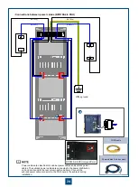
Ensure that the switch of the external power supply device is turned to the ‘OFF’ side.
If a power monitoring device is installed to the power supply device, disconnect the power supply device
and the power monitoring device before the test. Otherwise, the test result may be not correct.
Turn the subrack power switch to the ‘OFF’ side.
The switch is on the DC PDU, which is on the top of the cabinet.
Use the multimeter to test the resistance between the NEG(-), RTN(+) and PGND. The value should be
∞.
Turn the subrack power switch to the ‘ON’ side. The switch is on the DC PDU, which is on the top of the cabinet.
Use the multimeter to test the resistance between the the NEG(-), RTN(+) and PGND. The value should be more
than 20 kilohms.
Turn the switches of all the subracks to the ‘OFF’ side.
If the test result shows that the resistance is less than 20 ohms, it indicates that a short circuit occurs between
the working power and the working ground. In this case, rectify the fault and perform step 4 again.
Power sockets 1-4
(left)
RTN1(+)
RTN2(+)
NEG1(-)
NEG2(-)
Power sockets 1-4
(right)
Power switches SW1-SW4 (left) PGND bolt
Power switches SW1-SW4 (right)
•
DPD100-2-8 PDU
•
N1PDU
Power output area (A)
Power output area (B)
Power input area (A)
Power input area (B)
A-NEG1-4 (-)
B-NEG1-4 (-)
A-RTN1(+)
B-RTN1(+)
DPD100-2-8 PDU Ground Point
Summary of Contents for OptiX OSN 2500
Page 1: ...HUAWEI TECHNOLOGIES CO LTD OptiX OSN 2500 Quick Installation Guide Issue 12 Date 2017 09 30 ...
Page 19: ...16 Cable Connections c COA power interface F f cable a b a b COA power cable ...
Page 36: ...33 Upward Cabling c Cable distribution plate To the alarm monitor SEI board ...
Page 37: ...34 Downward cabling d Cable distribution plate SEI board To the alarm monitor a a ...

