56
Name
Content
Example
Remarks
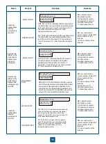
Labels for
optical fibers
from the
equipment to
the ODF
MN-B-C-D-R/T
MN: cabinet number
B: subrack number
C: physical slot number
D: network port number
R: optical receive port
T: optical transmit port
ODF-MN-B-CR/T
MN: row number and
column number of the ODF
B: row number of the
terminal
C: column number of the
terminal
Engineering
labels for the
trunk cables
between two
pieces of
equipment
MN-B-C-D-R/T
MN: cabinet number
B: subrack number
C: physical slot number
D: cable number
R: optical receive port
T: optical transmit port
Engineering
labels for the
trunk cables
between the
equipment and
the DDF
DDF-MN-BC-
D/R/T
MN: row number and
column number of the DDF
B: row number of the
terminal
C: column number of the
terminal
D: direction A or B
R: optical receive port
T: optical transmit port
Labels for
optical fibers
from the
equipment to
the ODF
MN-B-C-D-R/T
MN: cabinet number
B: subrack number
C: physical slot number
D: network port number
R: optical receive port
T: optical transmit port
ODF-MN-B-CR/T
MN: row number and
column number of the ODF
B: row number of the
terminal
C: column number of the
terminal
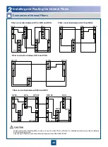
ODF-G01-01-01-R: indicates that the local end of
the optical fiber is connected to the optical receive
port on the terminal in row 01 and column 01 of
the ODF in row G and column 01 in the
telecommunications room.
A01-01-05-05-R: indicates that the opposite end of
the optical fiber is connected to optical receive
port 05 in slot 05 of subrack 01 in the cabinet in
row A and column 01 in the telecommunications
room.
To:
A0
1
-
-
- -
-
-
-
-
01
05
ODF G01 01 01 R
05
R
G01-01-05-12-T: indicates that the local end of
the trunk cable is connected to the optical
transmit port of trunk cable 12 in slot 5 of
subrack 01 in the cabinet in row G and column
01 in the telecommunications room.
DDF-G01-01-01-AR: indicates that the opposite
end of the trunk cable is connected to the optical
receive port of the terminal in direction A (for
connection to the optical network equipment) in
row 01 and column 01 on the DDF in row G and
column 01 in the telecommunications room.
To:
D0
2
-
-
- -
-
-
-
-
01
01
G01 01 05 12 T
01
R
To:
DDF
-
-
-
-
G01
01
A01 03 01 01 R
01 AR
-
-
-
-
ODF-G01-01-01-R: indicates that the local end
of the optical fiber is connected to the optical
receive port on the terminal in row 01 and
column 01 of the ODF in row G and column 01
in the telecommunications room.
A01-01-05-05-R: indicates that the opposite
end of the optical fiber is connected to optical
receive port 05 in slot 05 of subrack 01 in the
cabinet in row A and column 01 in the
telecommunications room.
To:
A0
1
-
-
- -
-
-
-
-
01
05
ODF G01 01 01 R
05
R
Summary of Contents for OptiX OSN 2500
Page 1: ...HUAWEI TECHNOLOGIES CO LTD OptiX OSN 2500 Quick Installation Guide Issue 12 Date 2017 09 30 ...
Page 19: ...16 Cable Connections c COA power interface F f cable a b a b COA power cable ...
Page 36: ...33 Upward Cabling c Cable distribution plate To the alarm monitor SEI board ...
Page 37: ...34 Downward cabling d Cable distribution plate SEI board To the alarm monitor a a ...

