45
A
B
3
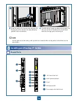
Installing and Routing Cabinet Indicator Cables
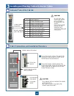
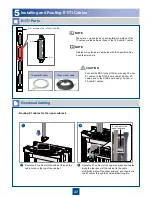
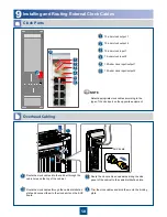
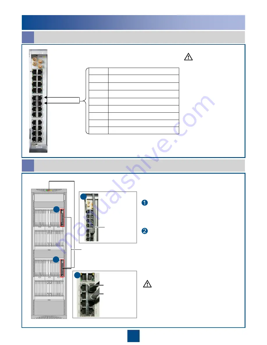
Indicator Ports of the Cabinet
a
Pin No.
Signal Designation
1
Positive critical alarm signals
2
Negative critical alarm signals
3
Positive major alarm signals
4
Positive power indicator signals
5
Negative power indicator signals
6
Negative major alarm signals
7
Positive minor alarm signals
8
Negative minor alarm signals
Do not connect other
cables to the indicator
ports or indicator
cascading ports of the
cabinet.
Ensure that no metallic
scraps exist at the
indicator ports or
indicator cascading ports
of the cabinet.
Indicator ports of
the cabinet
Indicator cascading
ports of the cabinet
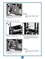
Cable Connections and Installation Procedure
b
A
B
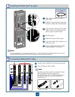
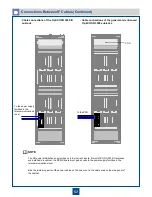
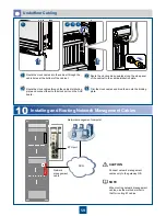
Connect the indicator cables of the cabinet to the
indicators of the cabinet and the LAMP1 port on
the AUX board of the lower subrack.
Indicator cables of the cabinet
Indicator cascading cables
between subracks
Connect the indicator cascading cables of the
cabinet to the LAMP1 port on the AUX board of the
upper subrack and the LAMP2 port on the AUX
board of the lower subrack.
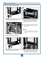
Only indicators can be connected to the indicator
ports of the cabinet.
Ensure that no metallic scrap exists at the
indicator ports of the cabinet.
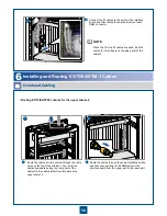
A
To the lower
subrack
B
To the indicators
of the cabinet
To the upper
subrack
CAUTION
CAUTION

