61
12
Installing and Routing Cables for PCM Boards
This section describes how to install and route cables for PCM boards in an OptiX OSN 3500 subrack with 14
PCM boards (seven on the right and seven on the left), one system control board, and one line board.
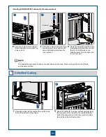
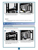
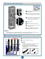
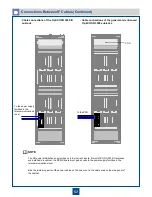
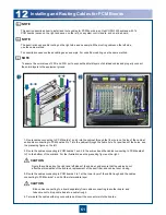
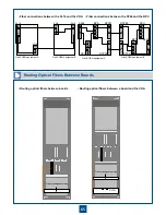
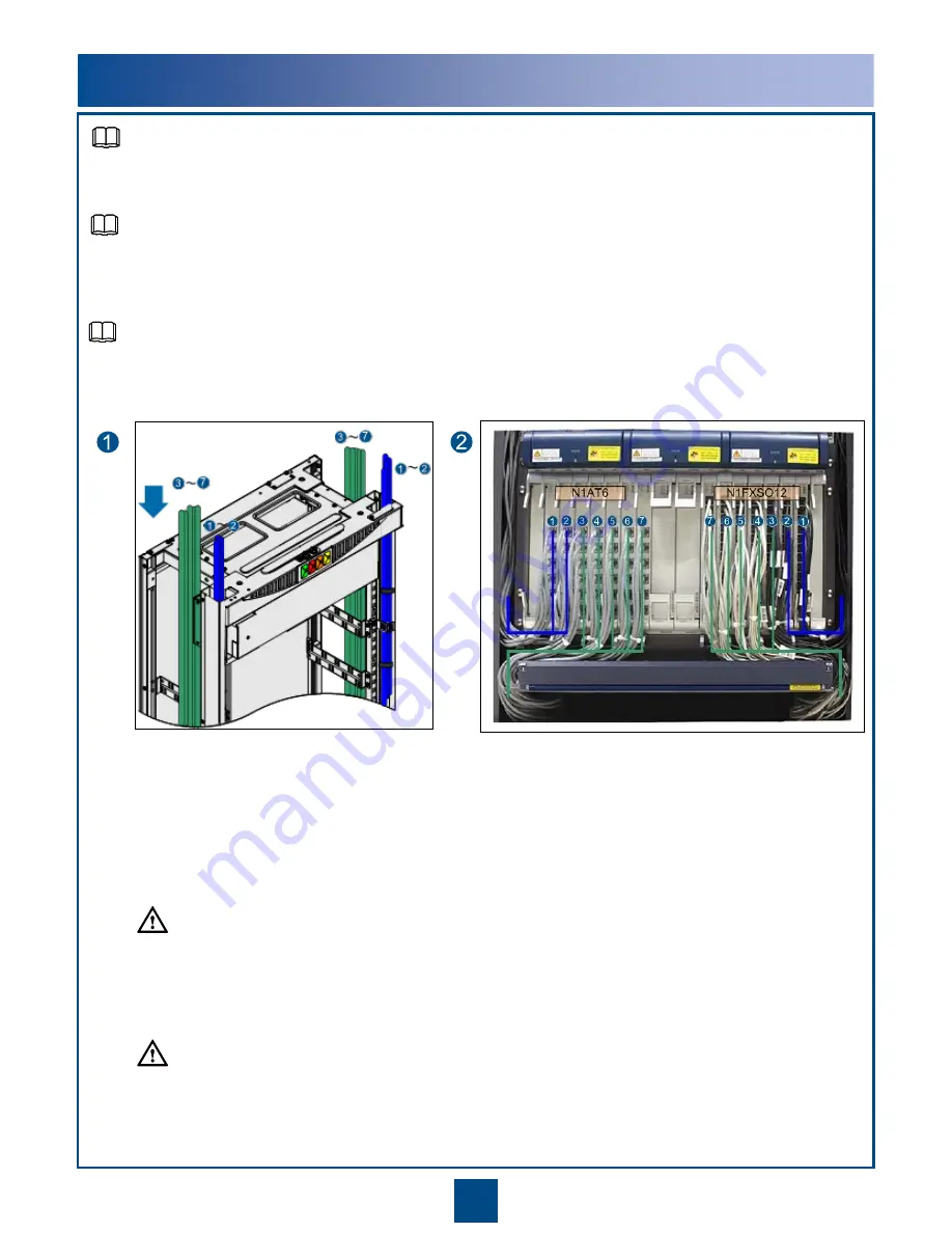
1. Route cables connecting to PCM boards 1 and 2 into the cabinet through the fiber hole on the top of the cabinet
and cables connecting to PCM boards 3 to 7 into the cabinet through the cable hole. For positions of the holes, see
the preceding figure on the left.
2. Route the cables connecting to PCM boards 1 and 2 to the subrack and the cables connecting to PCM boards 3
to 7 to the bottom of the subrack. For the illustration, see the preceding figure on the right.
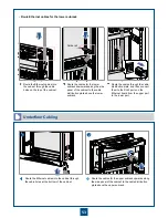
3. Route the cables connecting to PCM boards 3 to 7 at the lower layer of the cable trough and the cables
connecting to PCM boards 1 and 2 at the intermediate layer.
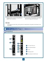
4. Terminate the cables with plug connectors and insert the connectors into the boards.
The description uses cable routing on the right side as an example. When routing cables on the left side,
use the same method.
The description uses overhead cabling as an example. For underfloor cabling, use the same method.
Route the cables along the right and left sides of the cabinet, and ensure that the cables do not
affect heat dissipation of the subrack, replacement of the dust filter, and cabinet door closing.
Bind cables connecting to a board separately from cables connecting to another board, and
take care not to drop cable ties into a cable trough.
NOTE
NOTE
CAUTION
CAUTION
To ensure the normal use of FXS and FXO ports, expose the shield layers of shielded cables and properly connect
the shield layers to the equipment ground.
NOTE

