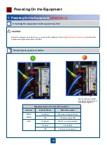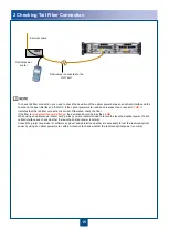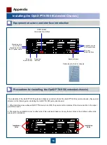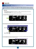
2
1
7
Make a proper terminal for the power cable end
according to the electrical power cable processing
specifications. Then, insert the power cable in the
DC connector according to the wiring sequence.
-
48 V power
cable (blue)
0 V power cable (black)
Insert the conductive part of the bare crimp
terminal of the power cable in the DC connector,
and then tighten the screws.
The preceding two operations are optional. Consult with the engineering supervisor to decide whether to
perform the operations.
NEG2(-)
INPUT
RTN2(+)
RTN1(+)
NEG1(-)
ON
OFF
20A
32A
32A
20A
ON
OFF
1
2
3
4
1
2
3
4
20A
32A
32A
20A
OUTPUT
OUTPUT
A
B
NEG(-)
Check the fuse current of the external power supply.
3
Installing the Power Cable (Mandatory)
Check the voltage of the external power supply.
- 48 V to - 72 V
- 60 V
- 38.4 V to - 57.6 V
- 48 V
Standard Voltage of the Input Power
Allowable Voltage Range
When installing or routing cables, refer to the
engineering document
on site to install and connect the power cable
at
the opposite end
.
0.22
±
0.03 N·M
It is recommended that one circuit breaker (fuse) in the power distribution cabinet corresponds to one set of equipment
(subrack). That is, one circuit breaker in the power distribution cabinet outputs one channel of power supply, which is
provided to only one set of equipment instead of multiple sets of equipment. If one circuit breaker in the power
distribution cabinet corresponds to multiple sets of equipment, when overcurrent occurs on one set of equipment, the
circuit breaker may perform the protection operation. Hence, the power of multiple sets of equipment fails.
The working current of the fuse on the power distribution cabinet may be affected by certain factors such as
temperature. Hence, derating should be adopted during design of power distribution.
Max. Power Consumption
Max. Working Current
Recommended Fuse Capacity
250 W
6.5 A
≥ 8 A
RTN(+)


