16
Installing the OptiX PTN 950 (Extended Chassis)
Appendix
a
a
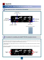
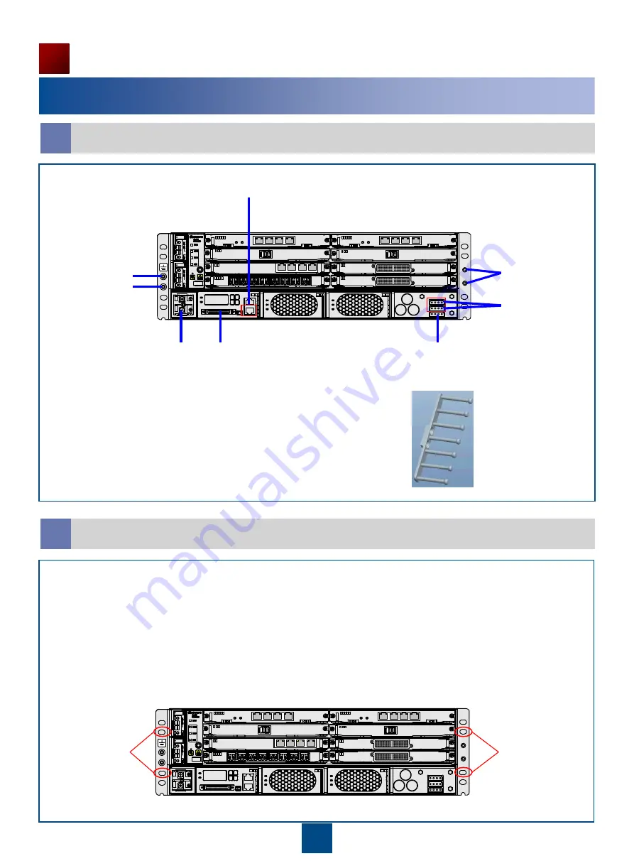
Equipment structure and interface introduction
a
b
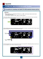
Precautions for installing the OptiX PTN 950 (extended chassis)
The installation of the OptiX PTN 950 (extended chassis) is similar to that of the OptiX PTN 950 (common chassis). Pay special
attention to the following when installing the OptiX PTN 950 (extended chassis):
2. There are four installation holes on either side of the extended chassis, and only the two holes in the middle on either side
are used for installation.
1. When installing a case-shaped OptiX PTN device in an IMB, the power and fan modules of the device must be in the upper
part of the device.
DC power
output interface
AC power
input interface
Battery interface
RS232/RS485
Communication interface
Installation
holes
Reserved
interface
Cable tray for the 3 U chassis
Grounding hole for
the AC power cable
Grounding hole
for the device
Installation
holes
Installation holes
for the cable tray


