background image

8

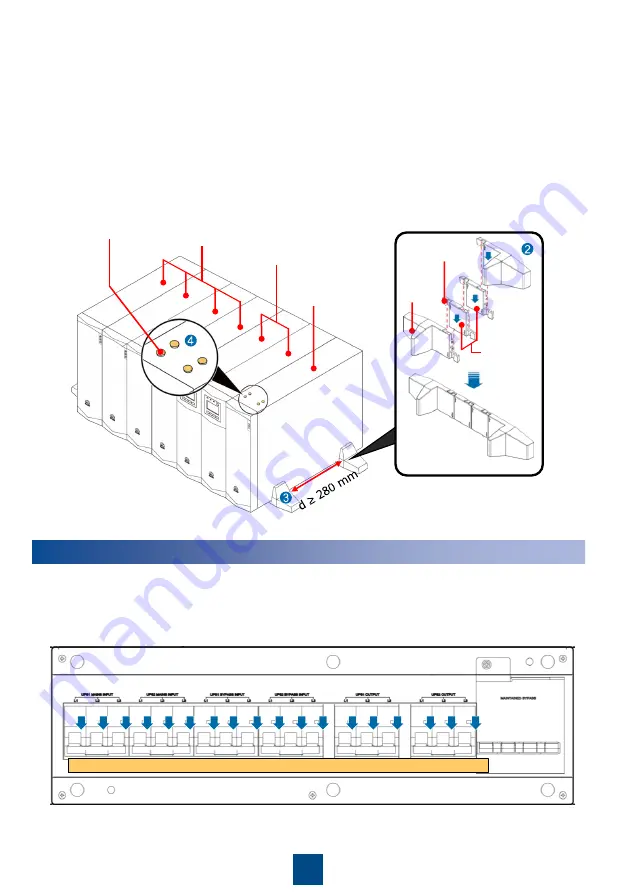
2. Assemble support bases. When you assemble two support bases, align connecting 

buckles with holes and insert the buckles vertically, as shown in the following figure.

3. Install two support bases for each group of devices. Place the support bases on the floor, 

determine the distance (greater than or equal to 280 mm) between the support bases, 

place devices on the support bases, and secure them.

4. Install two support bases for each group of devices. Place the support bases on the floor, 

determine the distance (greater than or equal to 280 mm) between the support bases, 

place devices on the support bases, and secure them.

Support 

base

Connecting 

buckle

Componen

ts installed 

between 

support 

bases

3 U battery 

packs

3 U UPSs

3 U PDC-

0038V4ACIOA

Rubber plugs

Cable Installation

1. Remove the front panel from the PDU and open the circuit breakers.

OFF

5

Summary of Contents for PDC-0038V4ACIOA

Page 1: ...egulations and design production and usage standards Local Safety Regulations When operating Huawei equipment you must follow the local laws and regulations Personnel Requirements 1 Only trained and qualified personnel are allowed to install operate and maintain Huawei equipment and they must understand basic safety precautions 2 You can modify default parameters only after being granted approval ...

Page 2: ...m x 585 mm Front panel under the cover 1 UPS 1 mains input circuit breaker 2 UPS 2 mains input circuit breaker 3 UPS 1 bypass input circuit breaker 4 UPS 2 bypass input circuit breaker 5 UPS 1 output circuit breaker 6 UPS 2 output circuit breaker 7 Maintenance bypass circuit breaker 8 Maintenance bypass circuit breaker cover 1 2 3 4 5 6 7 8 2 ...

Page 3: ...t group 1 250 V AC 15 A 8 Output socket group 1 fuses 9 Output socket group 2 fuses 10 Output socket group 2 250 V AC 10 A 11 UPS 1 mains input port 12 UPS 2 mains input port 13 UPS 1 bypass input port 14 UPS 2 bypass input port 15 UPS 1 output port 16 UPS 2 output port Precautions Tools 3 1 Get installation tools insulated to prevent electric shocks 3 4 5 6 7 16 15 14 13 12 11 10 9 8 2 1 3 ...

Page 4: ...he PDU appearance for shipping damage If any shipping damage is found report it to the carrier immediately 2 Check the PDU bar code and ensure that it complies with the order Check against the delivery list that the types of fittings are complete and correct If there is any discrepancy contact your local Huawei office immediately Device Movement Regulations 3 3 Do not move the PDU by holding its m...

Page 5: ...e floating nuts are delivered with the adjustable guide rails 2 Before you install guide rails accurately calculate the distance 3 U between the upper and lower guide rails A Attach the mounting brackets for the adjustable guide rails to mounting bars B Install floating nuts by using a flat head screwdriver This document uses a 19 inch rack as an example For other racks see the related UPS quick i...

Page 6: ...ustable guide rail A B 3 Place the PDU on the guide rails Secure the PDU to the rack using M6x16TM screws through the holes in the mounting brackets Do not move the PDU by holding its mounting brackets front panel or terminal cover When you move it see the movement regulations ...

Page 7: ...attery pack 3 Optional 3 U battery pack 4 Tower mounting the PDU 4 2 1 The support base length is adjustable You can add components to increase the length 2 Exert force to disassemble components in the reverse directions of assembling 1 When you change from rack mounting to tower mounting rotate the logo anticlockwise 90 degrees ...

Page 8: ... the support bases place devices on the support bases and secure them 4 Install two support bases for each group of devices Place the support bases on the floor determine the distance greater than or equal to 280 mm between the support bases place devices on the support bases and secure them Support base Connecting buckle Componen ts installed between support bases 3 U battery packs 3 U UPSs 3 U P...

Page 9: ...m of UPS2000 G 15 kVA or UPS2000 G 20 kVA three phase input three phase output 1 The table lists only the cables directly connected to the PDU For details about other cables and cable types see the quick installation guides for related devices 2 Configure colors for the cables prepared onsite in accordance with the local regulations 3 If customers purchase input and output power cables by themselv...

Page 10: ...ins input power cable N A Separately delivered with the PDU 6 UPS 1 AC output power cable N A Separately delivered with the PDU 7 UPS 2 bypass input power cable N A Separately delivered with the PDU 8 UPS 2 mains input power cable N A Separately delivered with the PDU 9 UPS 2 AC output power cable N A Separately delivered with the PDU 10 Maintenance bypass port cable RVV 4x0 5 Prepared onsite conn...

Page 11: ...ree phase output 10 3 2 1 9 6 7 4 8 5 11 The preceding figure shows how to connect cables when there are two mains inputs In the case of one mains input connect the mains input power cables to the AC BYPASS INPUT ports the AC MAINS INPUT ports are not connected Power On Procedure For details see the UPS2000 G 15 kVA 20 kVA Quick Guide 6 AC MAINS INPUT AC BYPASS INPUT AC OUTPUT ...

Page 12: ...er The procedure is as follows 1 Open the maintenance bypass circuit breaker cover on the PDU front panel The UPS generates the Maint Breaker close alarm the Alarm indicator is on and the buzzer buzzes and transfers to bypass mode Procedure to view the alarm 2 Close the maintenance bypass circuit breaker on the PDU front panel 3 Open the UPS input and output circuit breakers on the PDU front panel...

Page 13: ...U and the UPS Hot swap terminals 5 Use a multimeter to check that the UPS input and output voltages are 0 You can maintain the UPS Huawei Technologies Co Ltd Huawei Industrial Base Bantian Longgang Shenzhen 518129 People s Republic of China www huawei com ...

Reviews: