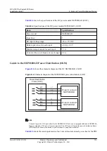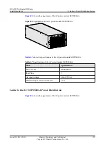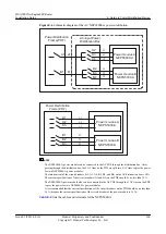
shows the schematic diagram of the DC power module NEPS5000-D (5 KW).
Figure E-2
Schematic diagram of the DC NEPS5000-D (5 KW)
Power moudue A
NEPS5000-D
Power moudue B
NEPS5000-D
a1
a3
a2
b3
b2
b1
Power Destribution
Frame (PDF)
A1
A3
A2
B3
B2
B1
NOTE
You need to provide 3 DC power lines for the NEPS5000-D. If a device is equipped with double NEPS5000-
D power modules, 6 DC power lines are required. The 6 DC power lines of the power distribution frame
(PDF) are directly connected to power module A and power module B.
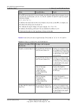
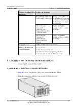
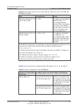
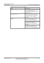
shows the current parameters of each circuit breaker and each power line for the PDF
Table E-2
Current parameters of each circuit breaker and each power line for the PDF (DC
NEPS5000-D (5 KW) )
Item
Specification
Note
Each circuit breaker (A1, A2,
A3, B1, B2, and B3)
≥
60 A
To protect power supplies of
different levels, it is
recommended that the
current of the circuit breaker
on the user side should be
greater than or equal to that of
the circuit breaker of the
power module (60 A).
Each power input (A1, A2,
A3, B1, B2, and B3)
≥
44 A @ -48 VDC
To support the maximum
configuration, it is
recommended that each DC
power line should provide a
minimum of 44 A @ -48
VDC current.
HUAWEI NetEngine80E Router
Installation Guide
E Guide to Power Distribution Design
Issue 02 (2011-09-10)
Huawei Proprietary and Confidential
Copyright © Huawei Technologies Co., Ltd.
153


