Installation Manual – Antenna & Feeder System Installation
BTS3802C & RRU
Chapter 3
Installing GPS Antenna & Feeder System
3-8
between the two hoops should not be less than 40cm, and their positions on the
wall should be kept evenly and symmetrically from the upper to the lower.
3) Drill holes at the place where marks exist. Since the specification of the
expansion bolt is M10, the
Y
12 drill bit may be adopted. Add rubber washer to
increase the stability when using fixing hoop to fasten the antenna pole.
4) After the installation, the pole should not get loosed when being pulled and
rotated the pole by hand. Check whether the antenna is erected vertically, and
the included angle between the support lever and the direction of the plummet is
less than 5°.
3.7 Installing GPS Antenna
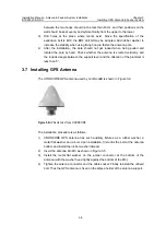
The UTONCORE GPS antenna used by mini NodeB is shown in Figure 3-6.
Figure 3-6
GPS antenna of Type UNONCORE
The installation procedure is as follows.
1) UNONCORE GPS antenna has such auxiliary fixtures as a rubber washer, a
metal flat washer and a bolt. Upon installation, first unfix the bolt at the antenna
bottom and install the rubber washer instead.
2) Insert the antenna into M3 as shown in Figure 3-5.
3) Install the metal flat washer on the jumper connector at the bottom of the
antenna (with the washer head tightly against the bottom of the M3).
4) Tighten the antenna connector and the cable socket. Finally reinstall the unfixed
bolt. Thus the GPS antenna is fixed on the ellipse holder of the antenna support.


