Installation Manual – Antenna & Feeder System Installation
BTS3802C & RRU
Chapter 3
Installing GPS Antenna & Feeder System
3-12
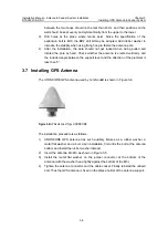
cable ties, there should be a slack of 5~10 mm left lest the cable ties fall off the
jumper due to temperature change.
3.11 Routing Feeders
Prior to feeder routing, carefully check the routing environment including the tower
and roof, etc. Determine the routing scheme and sequence as per the engineer
drawing.
z
The route leading the feeder from the installation hole to the equipment room
where cabinet equipment is located should be clear and can be fixed easily and
properly, meeting the cabling requirements in the equipment room. And reliable
rainproof and anticorrosive measures are available.
z
1.5m jumper should be bound at the outside of the antenna support lever evenly
using cable ties. In addition all cable ties should be fastened, with a same
spacing of 200mm. The direction of the cable tie heads should be consistent,
and all the ties should be cut fully to keep the jumper surface smooth.
z
When the antenna is installed on building roof, connectors at both ends of the
feeder should be protected with proper materials (such as packing bags for
board) to prevent damage to the connectors. The feeder should be fixed with
plastic clips attached with steel nails along the root of the wall on the building-top.
The spacing of the nails should be kept 1m. And the direction of the clip heads
should be interlaced regularly. If two feeders are joined, they should be bound
without intersection and curve
z
When routing the feeder, lay out the cable coil first and prevent bending as much
as possible. If bending cannot be avoided, the curve radius should not be less
than least radius allowed for each type of cable, so as to prevent cables being
damaged.
Caution:
When the distance from the antenna to the mini NodeB is greater than 100m, the 7/8 feeder should be
adopted so as to minimize signal loss, otherwise the 1/2 feeder should be selected.
3.12 Grounding Feeder
Feeder routing and GPS feeder grounding installation can be conducted
simultaneously. The following part describes feeder grounding according to different
installation modes.

