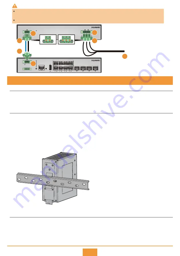
The PAC240S56-CN power module uses 220 V AC or 240 V DC input and provides four 56 V DC outputs. When
the S5720I-12X-PWH-SI-DC is installed in a scenario where 220 V AC or 240 V DC power is provided, the
PAC240S56-CN can be used to transfer power.
Before You Start
8 (Optional) Installing the PAC240S56-CN Power Module
Installing the PAC240S56-CN Power Module
Connecting the switch to the PAC240S56-CN Power Module
Use a wire stripper to peel about 7 mm length of insulation coating off one end of the positive and negative
cables. Insert the bare wires of the power cable into the Phoenix connector according to the sequence
shown in the figure, and tighten the screws to lock the cable.
Step 1
Place the real panel of the power module in front of the DIN rail, and ensure that the DIN rail fits in between
the fixture near the top of the DIN mounting kit and spring latch near the bottom.
Make the power module incline forward with the bottom away from the DIN rail, and place the fixture at
the rear of the DIN mounting kit on the top of the DIN rail.
Slowly push the switch toward the DIN rail to make the spring latch near the bottom of the DIN mounting kit move
down. The spring latch then bounces back to fix the switch on the DIN rail. If the spring latch is too tight to move
down, you can pull down the spring latch during the installation.
Step 1
Step 2
Step 3
7
S5720I-12X-PWH-SI-DC
1
2
3
4
5
6
7
8
1
2
3
4
MODE
CONSOLE
10/100/1000M PoE++
PNP
STCK
SPED
STAT
SYS
PWR
-
-/N
+
PoE
10G/1G
50~56 V; 5.5A
DI1- DI1+ DI2- DI2+
PAC-260WA-E
PWR
L
N
PE
INPUT: ~100-240 V; 50/60 Hz; 6 A
-
+
50~56 V; 6.79A
OUTPUT:
-
+
L N
PE
220 V AC mains
1
2
3
4
2
1
5
There is a risk of electric shock when handling the Phoenix connector. To avoid electric shock, ensure that the L/N/PE wires
are connected in sequence.
Ensure that there are no exposed metal parts after the power cable is connected to the Phoenix connector.
WARNING


