2
The S600-E series switches use forced or natural heat dissipation mode. If multiple switches are installed in a
cabinet/rack, leave at least 1 U distance between each two switches (1 U = 44.45 mm). This distance is
recommended for switches using forced heat dissipation, and is required for switches using natural heat
dissipation.
Grounding the switch helps protect it from lightning, electromagnetic interference, and electrostatic discharge,
and is the prerequisite for a PoE switch to provide power for a PD.
M4
1
2
Port side faces down
Expansion bolt
4 Installing the Chassis
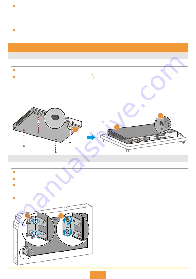
Scenario 1: Desk Mounting
Scenario 2: Wall Mounting
Do not stack fanless switches on top of or closely next to each other.
S600-E series switches provide a security slot ( ) near the panel on a side of the chassis. You can install a
security lock (separately purchased) in this slot to protect the switch against theft.
Before You Start
Installation Procedure
Attach four rubber pads to the bottom.
Place the chassis on a desk.
Use M4 screws to fix the mounting brackets on
both sides close to the port side.
Use a hammer drill with
φ
8 drill bit to drill holes
on the wall, and fix the switch on the wall with
expansion bolts.
Connect the ground cable to the ground point.
Step 1
Step 2
Step 1
Step 2
Step 3
(Optional) Install a security lock.
Connect the ground cable to the ground point.
Step 3
Step 4
1
3
2
Before drilling holes in a wall, make sure there are no power cables in the wall to avoid electric shock.
The port-side panel must face down to protect the ports from water damage.
Ensure that there are no flammable or explosive materials near the switch and no obstructions within 100 mm
around the switch.
The expansion bolts need to be purchased separately.
Before You Start


