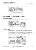
3
Cable Connections
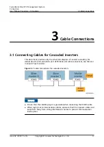
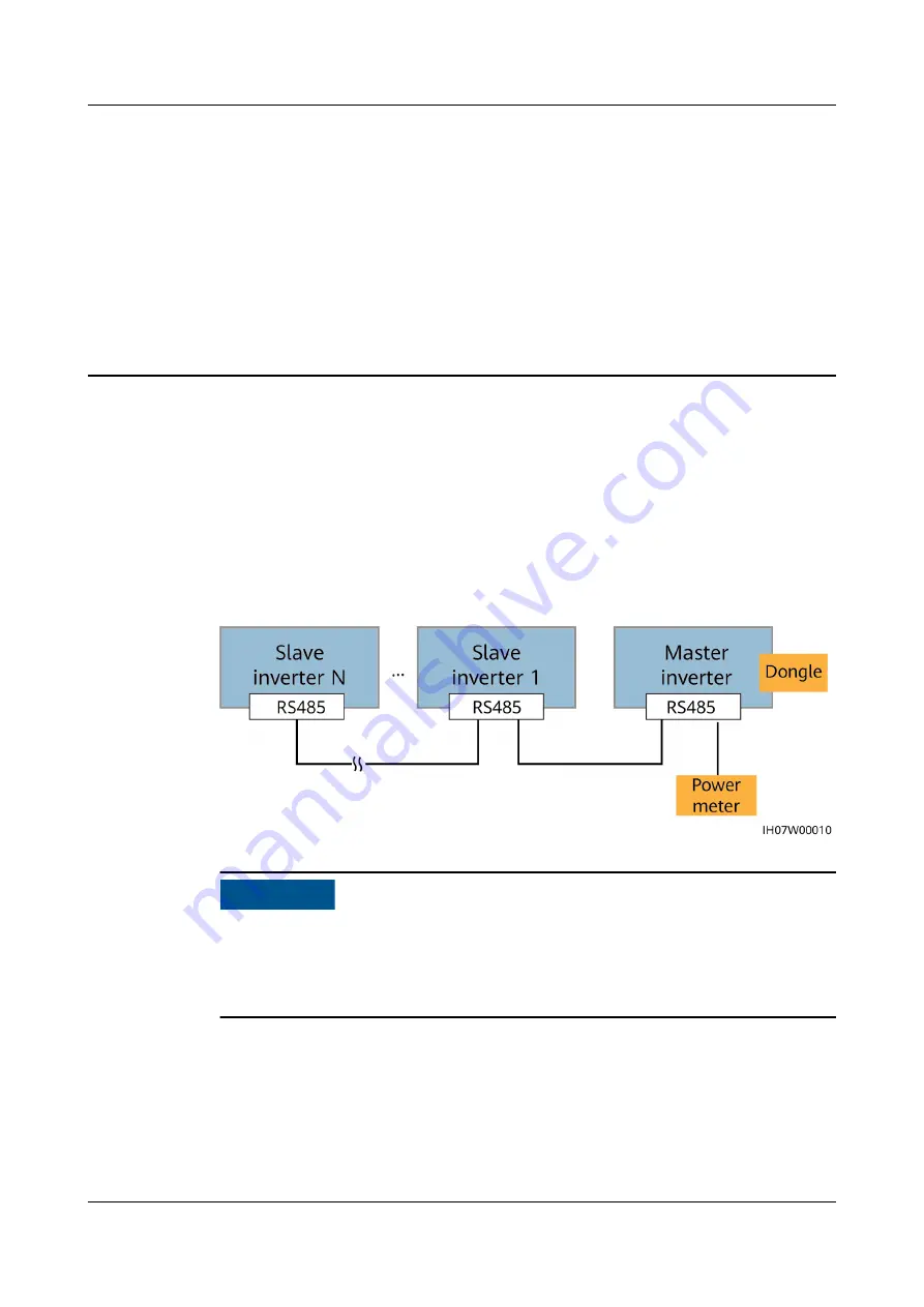
3.1 Connecting Cables for Cascaded Inverters
This document provides only the schematic diagram of inverter cascading. For
details about communications port definitions and cable connections, see the user
manual of each inverter.
Figure 3-1 Cable connections for cascaded inverters
NO TICE
● Ensure that the shielding layer is grounded when connecting the RS485 cable.
● When laying out communications cables, separate them from power cables and
keep them away from strong interference sources to prevent communication
interruption.
FusionSolar Smart PV Management System
Connection
User Manual (Inv SDongleA)
3 Cable Connections
Issue 02 (2021-11-25)
Copyright © Huawei Technologies Co., Ltd.
17


