6
Performing the Following Steps to Connect the MA5671 to Each Product
Based on the Preceding Cable Connections
Step 1
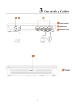
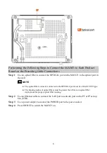
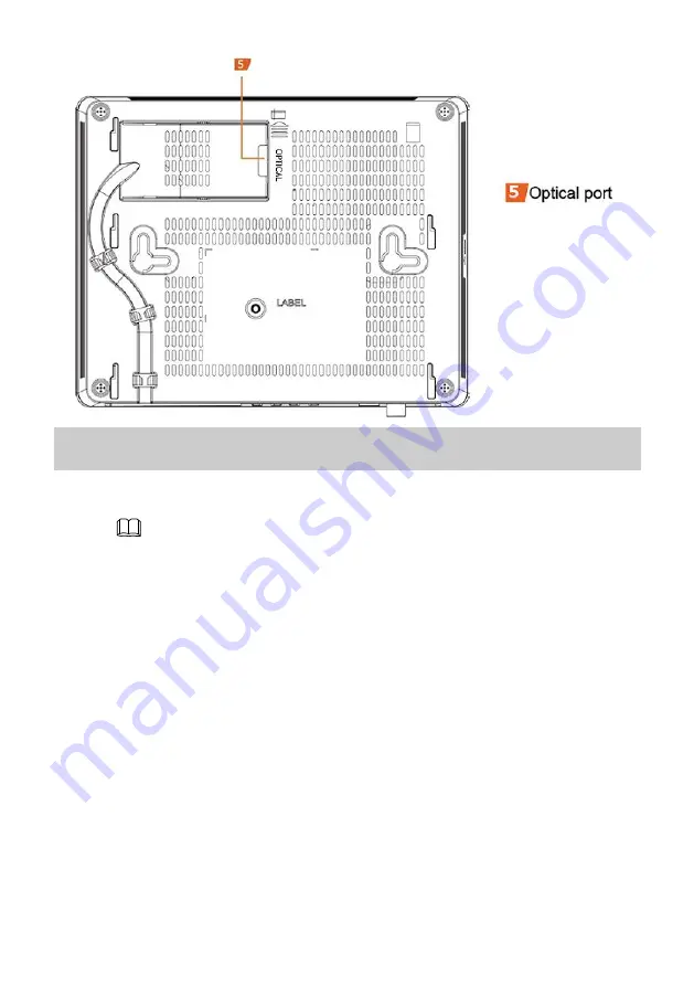
Use an optical fiber to connect the OPTICAL port on the MA5671 to the optical port in
the wall.
NOTE
The optical fiber connector connected to the OPTICAL port must be of the SC/UPC type
.
The bending radius of optical fibers must be greater than 30 mm in optical fiber
deployment for proper optical fiber running.
Step 2
Use an Ethernet cable to connect the LAN port to network port on the PC or IP set top
box (STB).
Step 3
Use a power adapter to connect the POWER port to the power socket.
Step 4
Press ON/OFF to switch the MA5671 on.


