10
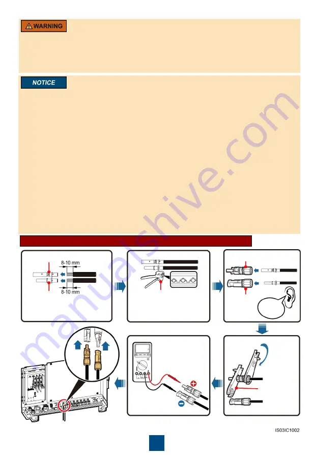
1. Use the positive and negative metal contacts and DC connectors supplied with the SUN2000. Using
other models of positive and negative metal contacts and DC connectors may result in serious
consequences. The caused device damage is not covered under any warranty or service agreement.
2. The metal contacts supplied with the DC connectors are either cold forming contacts or stamping
forming contacts. Crimp the metal cold forming contacts using crimping tool UTXTC0005 (Amphenol,
recommended) or H4TC0001 (Amphenol). Crimp the metal stamping forming contacts using crimping
tool H4TC0003 (Amphenol, recommended) or H4TC0002 (Amphenol). Choose the crimping tools that
fit the metal contacts.
3. Before connecting DC input power cables, label the cable polarities to ensure correct cable
connections. If the cables are connected incorrectly, the SUN2000 may be damaged.
4. Insert the crimped metal contacts of the positive and negative power cables into the appropriate
positive and negative connectors. Then pull back the DC input power cables to ensure that they
are connected securely.
5. Connect the positive and negative connectors to the appropriate positive and negative DC input
terminals. Then pull back the DC input power cables to ensure that they are connected securely.
6. If the DC input power cable is reversely connected, do not operate the DC switches and positive
and negative connectors immediately. Otherwise, the SUN2000 will be damaged. The caused
equipment damage is beyond the warranty scope. Wait until the solar irradiance declines at night
and the PV string current reduces to below 0.5 A. Then, turn off the two DC switches, remove the
positive and negative connectors, and correct the polarity of the DC input power cable.
• Ensure that the PV module output is well insulated to ground.
• Before inserting the positive and negative connectors respectively into the positive and negative
DC input terminals of the SUN2000, check that the DC voltage does not exceed 1100 V DC
using a multimeter and that the cables are connected correctly. Otherwise, the SUN2000 will be
damaged.
Positive connector
Negative
connector
Positive metal contact
Negative metal contact
Recommended: PV cable
(PV1-F) with a cross-
sectional area of 4 mm
2
.
Ensure that the cable
cannot be removed after
crimped.
Click
Ensure
that the
locking nut
is secured.
H4TW0001
(Amphenol)
UTXTC0005 (Amphenol)
Ensure that cables
are connected
correctly and that
the voltage does not
exceed 1100 V DC.
Installing a DC input power cable (using metal cold forming contacts)


