14
(Optional) Installing FE Communications Cables
4.7
FE communication is mainly used in distributed rooftop scenarios with a small number of SUN2000s. The
SUN2000 can directly connect to the PC over the Ethernet to implement monitoring networking.
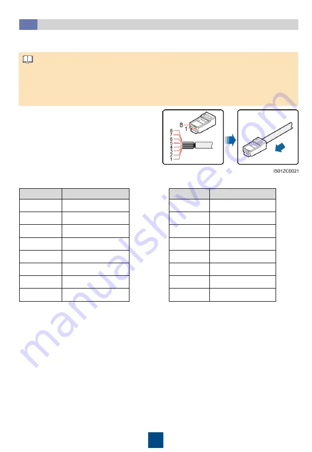
1. Insert the wires of the network cable to the
RJ45 connector in sequence.
You are recommended to use a CAT 5E outdoor
shielded network cable with an outer diameter
less than 9 mm and internal resistance not
greater than 1.5 ohms/10 m, as well as a
shielded RJ45 connector.
2. Crimp the RJ45 connector using a crimping tool.
1. If FE communication is used, a maximum of ten SUN2000s can be connected. In addition, the
NetEco needs to be installed on the PC for monitoring networking.
2. A standard network cable has two wire sequence standards, namely, 568A and 568B. The
network cables used in the same PV grid-tied power generation system should comply with the
same wire sequence standard.
NOTE
No.
Color
1
White-and-green
2
Green
3
White-and-orange
4
Blue
5
White-and-blue
6
Orange
7
White-and-brown
8
Brown
a. 568A standard
b. 568B standard
No.
Color
1
White-and-orange
2
Orange
3
White-and-green
4
Blue
5
White-and-blue
6
Green
7
White-and-brown
8
Brown
3. Remove the locking cap from the COM1 connector at the SUN2000 bottom and then remove
the plug from the cap.
4. Route the communications cables through the locking cap and then the COM1 connector at the
SUN2000 bottom.


