7
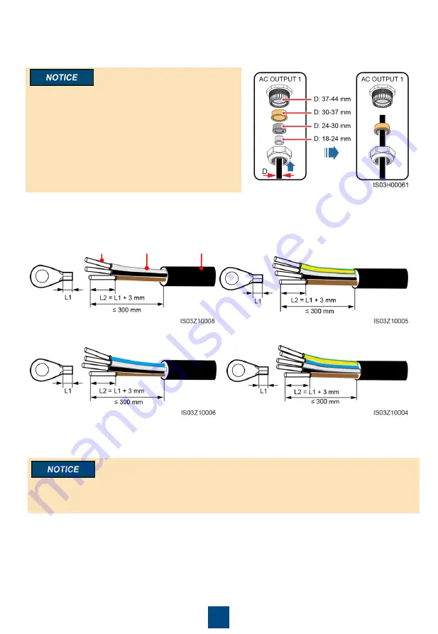
a. Three-core cable (excluding the ground
cable and neutral wire)
c. Four-core cable (excluding the ground
cable but including the neutral wire)
Jacket
Insulation layer
Core wire
b. Four-core cable (including the ground cable
but excluding the neutral wire)
d. Five-core cable (including the ground cable
and neutral wire)
4. Remove the locking cap from the AC OUTPUT 1 connector and then remove the plug.
5. Select an appropriate rubber fitting based on the cable outer diameter. Route the cable through
the locking cap and then the rubber fitting.
• Mismatch between the cable outer diameter and
the rubber fitting may degrade the Ingress
Protection Rating of the device.
• To avoid damaging the rubber fitting, do not
route a cable with a crimped OT terminal directly
through the rubber fitting.
• Do not adjust the cable when the locking cap is
tightened. Otherwise, the rubber fitting will shift,
which affects the Ingress Protection Rating of
the device.
6. Remove an appropriate length of the jacket and insulation layer from the AC output power cable
using a wire stripper. (Ensure that the jacket is in the maintenance compartment.)
7. Insert the exposed core wires into the crimping area of the OT terminal and crimp them using
hydraulic pliers.
8. Wrap the wire crimping area with heat shrink tubing or PVC insulation tape.
If heat shrink tubing is used, route the AC output power cable through the heat shrink tubing and
then crimp the OT terminal. Ensure that the area wrapped by the heat shrink tubing does not
exceed the crimping area of the OT terminal.
9. Route the AC output power cable through the AC OUTPUT 1 connector at the bottom of the
enclosure.
10.Connect the AC output power cable to the AC terminal block, and then secure the connector
using a 13 mm socket wrench with an extension rod. If you connect a ground cable to the
ground point in the maintenance compartment, tighten the ground screw using a 10 mm socket
wrench with an extension rod.


