background image

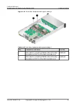
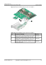
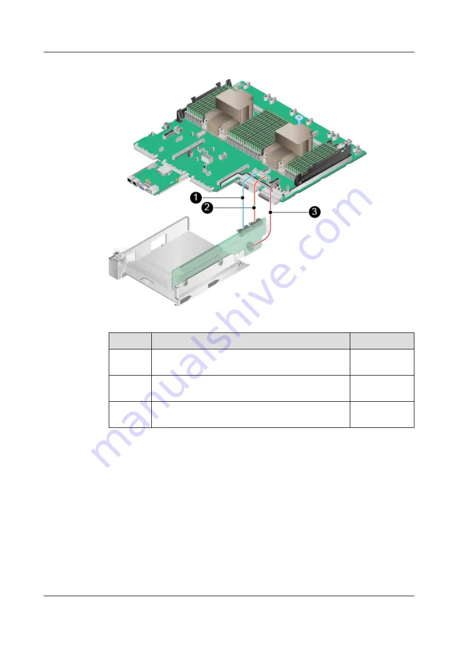
Figure 3-23 Internal cabling for the riser card in I/O module 3

Table 3-23 Internal cabling for the riser card for I/O module 3

No.

Connectors and Cable

Part No.

1

Signal cable for connecting Slimline B (J51) of the

mainboard to Slimline B (J401) of the riser card

04052304

2

Signal cable for connecting Slimline A (J52) of the

mainboard to Slimline A (J402) of the riser card

04052304

3

Power cable for connecting the mainboard (J12) to

the riser card (J701)

04052302

TaiShan 200 Server

Maintenance and Service Guide (Model 2280)

3 Internal Cabling

Issue 04 (2020-01-16)

Copyright © Huawei Technologies Co., Ltd.

63

Summary of Contents for TaiShan 200 2280

Page 1: ...TaiShan 200 Server Maintenance and Service Guide Model 2280 Issue 04 Date 2020 01 16 HUAWEI TECHNOLOGIES CO LTD ...

Page 2: ...s document may not be within the purchase scope or the usage scope Unless otherwise specified in the contract all statements information and recommendations in this document are provided AS IS without warranties guarantees or representations of any kind either express or implied The information in this document is subject to change without notice Every effort has been made in the preparation of th...

Page 3: ...ined as follows Symbol Description Indicates a hazard with a high level of risk which if not avoided will result in death or serious injury Indicates a hazard with a medium level of risk which if not avoided could result in death or serious injury Indicates a hazard with a low level of risk which if not avoided could result in minor or moderate injury Indicates a potentially hazardous situation wh...

Page 4: ...onfigure the server with Kunpeng 920 5220 or 3210 processors Added information about iBMC V500 and later versions 03 2019 12 17 Added the server with 24 x 2 5 SAS SATA pass through drives 02 2019 11 14 Changed the product name Added the FlexIO card with four 25GE optical ports 01 2019 07 01 This issue is the first official release TaiShan 200 Server Maintenance and Service Guide Model 2280 About T...

Page 5: ...ing 41 3 1 Internal Cabling for a Server with 12 x 3 5 inch Drives in Expander Mode 42 3 2 Internal Cabling for a Server with 12 x 3 5 inch Drives in Pass Through Mode 46 3 3 Internal Cabling for a Server with 25 x 2 5 inch Drives in Expander Mode 50 3 4 Internal Cabling for a Server with 8 x 2 5 inch SAS SATA Drives and 12 x 2 5 inch NVMe SSDs 54 3 5 Internal Cabling for a Server with 24 x 2 5 in...

Page 6: ...al Front Bezel 85 5 6 Drive 88 5 7 PSU 91 5 7 1 AC PSU 91 5 7 2 DC PSU 97 5 8 Chassis Cover 101 5 9 Air Duct 103 5 10 Fan Module 106 5 11 Riser Module 109 5 12 PCIe Card on a Riser Module 119 5 13 Battery 121 5 14 Screw in RAID Controller Card 124 5 15 Supercapacitor 127 5 16 DIMM 132 5 17 FlexIO Card 134 5 18 Front Drive Backplane 138 5 19 Rear Drive Module 141 5 19 1 2 x 3 5 inch Rear Drive Modu...

Page 7: ...4 2 Logging In to the Server Using the IRC 180 8 5 Logging In to the Server over a Serial Port Using PuTTY 186 8 6 Logging In to the Server over a Network Port Using PuTTY 188 8 7 Querying the Processor Model of a Server 190 A Appendix 195 A 1 Spare Parts Description 195 A 2 BIOS 196 A 3 iBMC 197 A 4 Glossary 198 A 5 Acronyms and Abbreviations 200 TaiShan 200 Server Maintenance and Service Guide M...

Page 8: ... 7260 5250 or 5230 processors the server provides 32 DIMM slots Figure 1 1 shows the components of the server Figure 1 1 Components server with Kunpeng 920 7260 5250 or 5230 processors 1 I O module 1 2 I O module 2 3 PSUs 4 Chassis 5 I O module 3 6 Supercapacitor bracket 7 Air duct 8 Front drive backplane 9 Fan module brackets 10 Fan modules TaiShan 200 Server Maintenance and Service Guide Model 2...

Page 9: ... of the server Figure 1 2 Components server with Kunpeng 920 5220 or 3210 processors 1 I O module 1 2 I O module 2 3 PSUs 4 Chassis 5 I O module 3 6 Supercapacitor bracket 7 Air duct 8 Front drive backplane 9 Fan module brackets 10 Fan modules 11 Front drives 12 Cable organizers 13 Heat sinks 14 DIMM 15 Mainboard 16 RAID controller card TaiShan 200 Server Maintenance and Service Guide Model 2280 1...

Page 10: ... drive modules or riser modules The preceding figure is for reference only CPUs are integrated on the mainboard and cannot be replaced independently Use the Intelligent Computing Spare Parts Checker to obtain information about the spare parts TaiShan 200 Server Maintenance and Service Guide Model 2280 1 Physical Structure Issue 04 2020 01 16 Copyright Huawei Technologies Co Ltd 3 ...

Page 11: ...ainboard and iBMC Card Connectors 2 9 DIMM 2 10 Riser Cards and PCIe Slots 2 11 Fan Modules 2 1 Front Panel Components For details about the drive numbers and types of 2280 see 2 6 1 Drive Slot Numbers Figure 2 1 shows the components on the front panel of a server with 12 x 3 5 inch drives TaiShan 200 Server Maintenance and Service Guide Model 2280 2 Components Issue 04 2020 01 16 Copyright Huawei...

Page 12: ... Drive 2 VGA port 3 USB 3 0 port 4 Label plate with an SN label Figure 2 3 shows the components on the front panel of a server with 8 x 2 5 inch SAS SATA drives and 12 x 2 5 inch NVMe SSDs Figure 2 3 Components on the front panel of a server with 8 x 2 5 inch SAS SATA drives and 12 x 2 5 inch NVMe SSDs 1 Drive 2 Filler panel 3 VGA port 4 USB 3 0 port 5 Label plate with an SN label TaiShan 200 Serv...

Page 13: ...ort USB 3 0 The USB ports allow USB devices to be connected to the server NOTE Before connecting an external USB device check that the USB device functions properly A server may operate abnormally if an abnormal USB device is connected If an external USB device is used the maximum length of the extension cable is 1 m VGA port DB15 The VGA port is connected to a terminal such as a monitor or physic...

Page 14: ...letters J to N indicate 2018 to 2022 and letters P to Y indicate 2023 to 2032 NOTE The years from 2010 are represented by upper case letters excluding I O and Z because the three letters are similar to digits 1 0 and 2 The second character indicates the month Digits 1 to 9 indicate January to September and letters A to C indicate October to December 5 Serial number six characters 6 RoHS compliance...

Page 15: ...diagnostic LED 5 FlexIO presence indicators 1 and 2 Figure 2 8 shows the indicators and buttons on the front panel of a server with 8 x 2 5 inch SAS SATA drives and 12 x 2 5 inch NVMe SSDs Figure 2 8 Indicators and buttons on the front panel of a server with 8 x 2 5 inch SAS SATA drives and 12 x 2 5 inch NVMe SSDs 1 UID button indicator 2 Health indicator 3 Power button indicator 4 Fault diagnosti...

Page 16: ...omponent is faulty For details about error code see the TaiShan Rack Server iBMC Alarm Handling Power button indicator Power indicator Steady yellow The server is in the standby state Steady green The server is properly powered on Blinking yellow The iBMC is starting Off The server is not connected to a power source Power indicator When the server is powered on you can press this button to shut do...

Page 17: ...turn on or off the UID indicator You can press and hold down this button for about 5 seconds to reset the iBMC Health indicator Steady green The server is operating properly Blinking red at 1 Hz A major alarm has been generated on the server Blinking red at 5 Hz A critical alarm has been generated on the server FlexIO presence indicators 1 and 2 1 and 2 The numbers 1 and 2 respectively represent F...

Page 18: ...appable If you need to replace it power off the server Table 2 4 Ports on the rear panel Port Type Quanti ty Description VGA port DB15 1 The VGA port is connected to a terminal such as a monitor or physical KVM USB port USB 3 0 2 The USB ports allow USB devices to be connected to the server NOTE Before connecting an external USB device check that the USB device functions properly A server may oper...

Page 19: ...orts 10 100 1000 Mbps auto negotiation 25GE optical port SFP28 4 A FlexIO card can provide a maximum of four 25GE optical ports NOTE The 25GE optical ports support rate adaptation to 10GE and optical modules of different rates are required PSU socket 1 2 Determine the number of PSUs based on actual requirements but ensure that the rated power of the PSUs is greater than that of the server You are ...

Page 20: ...n status indicator Steady green The network port is properly connected Off The network port is not connected UID indicator The UID indicator helps identify and locate a device Off The device is not being located Blinking blue blinking 255 seconds The device has been located and is differentiated from other devices that have also been located Steady blue The device is being located NOTE You can tur...

Page 21: ...protection or some component failures Blinking green at 1 Hz The input is normal the server is standby The input is overvoltage or undervoltage For details see TaiShan Rack Server iBMC Alarm Handling Blinking green at 4 Hz under online PSU firmware upgrade Off No power is supplied 2 5 FlexIO Cards For details about FlexIO cards supported by the server see the Intelligent Computing Compatibility Ch...

Page 22: ...ate indicator Steady green The data transmission rate is 25 Gbit s Steady yellow The data transmission rate is 10 Gbit s Off The network port is not connected Connection status indicator Data transmission status indicator Steady green The network port is properly connected Blinking green Data is being transmitted Off The network port is not connected 2 6 Drive Slot Numbers and Indicators 2 6 1 Dri...

Page 23: ... Disk40 12 41 Disk41 13 42 Disk42 14 43 Disk43 15 Figure 2 15 shows the drive slot numbers of a server with 12 x 3 5 inch drives in pass through mode Figure 2 15 Server with 12 x 3 5 inch drives in pass through mode Figure 2 16 shows the drive slot numbers of a server with 25 x 2 5 inch drives in Expander mode TaiShan 200 Server Maintenance and Service Guide Model 2280 2 Components Issue 04 2020 0...

Page 24: ...isk40 25 41 Disk41 26 Figure 2 17 shows the drive slot numbers of a server with 8 x 2 5 inch SAS SATA drives and 12 x 2 5 inch NVMe SSDs Figure 2 17 Server with 8 x 2 5 inch SAS SATA drives and 12 x 2 5 inch NVMe SSDs Figure 2 18 shows the drive slot numbers of a server with 24 x 2 5 SAS SATA passthrough drives TaiShan 200 Server Maintenance and Service Guide Model 2280 2 Components Issue 04 2020 ...

Page 25: ...ves I O module 3 2 4 NVMe SSDs One RAID controller card Server with 12 x 3 5 inch drives in pass through mode 3 12 SAS SATA drives I O module 2 2 SAS SATA drives I O module 3 2 4 NVMe SSDs CPU over SAS Server with 8 x 2 5 inch SAS SATA drives and 12 x 2 5 inch NVMe SSDs 1 20 Slots 0 to 7 support only SAS SATA drives Slots 8 to 19 support only NVMe SSDs 4 I O module 3 2 4 NVMe SSDs One RAID control...

Page 26: ... with Kunpeng 920 5220 or 3210 processors do not support the configuration of 24 x 2 5 inch SAS SATA pass through drives 2 6 2 SAS SATA Drive Indicators Figure 2 19 shows the SAS SATA drive indicators Figure 2 19 SAS SATA drive indicators Table 2 10 Description of SAS SATA drive indicators Drive Activity Indicator Green Indicator Drive Fault Indicator Yellow Indicator Description Steady on Off The...

Page 27: ...green 2 Hz Off Data is being read from or written to the NVMe SSD Off Blinking yellow 2 Hz The NVMe SSD is being located or hot swapped Off Blinking yellow at 0 5 Hz The NVMe SSD completes the hot removal process and is removable Steady green or off Steady yellow The NVMe SSD is faulty 2 7 Drive Backplane Connectors Figure 2 21 shows connectors on the backplane for 12 x 3 5 inch drives in pass thr...

Page 28: ...lane for 12 x 3 5 inch drives in Expander mode Figure 2 22 Backplane for 12 x 3 5 inch drives in Expander mode Part No 03024MSG 1 Low speed signal cable connector REAR BP0 J32 2 Mini SAS HD connector PORT A J28 3 Mini SAS HD connector PORT B J29 4 Mini SAS HD connector REAR PORT J31 5 Low speed signal cable connector HDD BP J1 6 Power connector POWER J24 7 Low speed signal cable connector REAR BP1...

Page 29: ... 24 Backplane for 8x 2 5 inch SAS SATA drives and 12 x 2 5 inch NVMe SSDs Part No 03025EUL 1 Slimline connector PORT 2C J31 2 Slimline connector PORT 1C J19 3 Slimline connector PORT 1B J18 4 Slimline connector PORT 1A J17 5 Mini SAS HD connector PORT B J16 6 Mini SAS HD connector PORT A J15 7 Low speed signal cable connector HDD BP J41 8 Power connector POWER J37 9 Slimline connector PORT 2A J21 ...

Page 30: ...RT2B J31 8 Mini SAS HD connector PORT3B J33 Figure 2 26 shows connectors on the backplane for two 3 5 inch rear drives Figure 2 26 Backplane for two 3 5 inch rear drives Part No 03026AJF 1 Low speed signal cable connector REAR BP J5 2 Mini SAS HD connector REAR PORT J2 3 Power connector BP PWR J1 Figure 2 27 shows connectors on the backplane for two 2 5 inch rear drives TaiShan 200 Server Maintena...

Page 31: ...drives Part No 03025VYV 1 Power connector REAR BP POWR3 J24 2 Slimline A connector SLIMLINE A J8 3 Slimline B connector SLIMLINE B J9 4 Mini SAS HD connector PORT A J2 5 Low speed signal cable connector HDD BP J23 2 8 Mainboard and iBMC Card Connectors Figure 2 29 shows the ports on the mainboard and iBMC card of a server with Kunpeng 920 7260 5250 or 5230 processors TaiShan 200 Server Maintenance...

Page 32: ...BMC card 7 Jumper J87 NOTE The COM_SW pin is used for changing the connection direction of the physical serial port The BMC_RCV PIN pin is used for restoring default iBMC settings 8 FlexIO card 1 connector J6008 9 System battery U53 10 Riser card slot 1 J6012 11 TPM J50 12 Riser card 1 power connector configured with four GPUs J6026 TaiShan 200 Server Maintenance and Service Guide Model 2280 2 Com...

Page 33: ...S connector CPU 2 J2022 24 Built in drive backplane power connector J11 25 Riser card 2 power connector J6021 26 Built in drive backplane low speed signal connector J49 27 Riser card 3 Rear drive backplane 3 power connector J12 28 Riser card 3 Rear drive backplane 3 Slimline connectors J52 and J51 from left to right 29 Power connector 2 J73 30 Power connector 1 J74 Figure 2 30 shows the ports on t...

Page 34: ...C card 7 Jumper J87 NOTE The COM_SW pin is used for changing the connection direction of the physical serial port The BMC_RCV PIN pin is used for restoring default iBMC settings 8 FlexIO card 1 connector CPU 1 J6008 9 System battery U53 10 Riser card slot 1 J6012 11 TPM J50 12 Riser card 1 power connector configured with four GPUs J6026 TaiShan 200 Server Maintenance and Service Guide Model 2280 2...

Page 35: ...6 Riser card 3 Rear drive backplane 3 power connector J12 27 Riser card 3 Rear drive backplane 3 Slimline connectors J52 and J51 from left to right 28 Power connector 2 J73 29 Power connector 1 J74 CPUs are integrated on the mainboard and cannot be replaced independently The iBMC card cannot be replaced independently Replace it with the mainboard 2 9 DIMM 2 9 1 DIMM Slot Numbers When configured wi...

Page 36: ...unpeng 920 7260 5250 or 5230 processors CPU Channel DIMM CPU1 TB_A DIMM060 G DIMM061 O TB_B DIMM020 C DIMM021 K TB_C DIMM040 E DIMM041 M TB_D DIMM000 A DIMM001 I TA_A DIMM030 D DIMM031 L TA_B DIMM070 H DIMM071 P TA_C DIMM010 B DIMM011 J TaiShan 200 Server Maintenance and Service Guide Model 2280 2 Components Issue 04 2020 01 16 Copyright Huawei Technologies Co Ltd 29 ...

Page 37: ..._C DIMM110 B DIMM111 J TA_D DIMM150 F DIMM151 N When configured with Kunpeng 920 5220 or 3210 processors the server provides 16 DDR4 DIMM slots Each processor supports four DIMM channels and each DIMM channel supports two DIMMs Figure 2 32 shows the DIMM slot numbers TaiShan 200 Server Maintenance and Service Guide Model 2280 2 Components Issue 04 2020 01 16 Copyright Huawei Technologies Co Ltd 30...

Page 38: ... 5220 or 3210 processors CPU Channel DIMM CPU1 TB_A DIMM060 G DIMM061 O TB_B DIMM020 C DIMM021 K TB_C DIMM040 E DIMM041 M TB_D DIMM000 A DIMM001 I TA_A DIMM030 D DIMM031 L TA_B DIMM070 H DIMM071 P TA_C DIMM010 B DIMM011 J TA_D DIMM050 F TaiShan 200 Server Maintenance and Service Guide Model 2280 2 Components Issue 04 2020 01 16 Copyright Huawei Technologies Co Ltd 31 ...

Page 39: ...number of DIMMs and the DIMMs are evenly distributed among the memory channels Unbalanced configuration reduces memory performance and is not recommended In unbalanced DIMM configuration DIMMs are not evenly configured for memory channels or processors If a processor is configured with 3 5 7 9 10 11 12 13 14 or 15 DIMMs the DIMMs are not evenly configured for memory channels If the processors in a...

Page 40: ...n installed in I O module 1 and PCIe slots 4 to 6 when installed in I O module 2 Figure 2 33 Riser card 1 three x8 slots The riser card shown in Figure 2 34 supports full height full length dual width GPUs It provides PCIe slots 2 and 3 when installed in I O module 1 and PCIe slots 5 and 6 when installed in I O module 2 The card must be used together with the power cables delivered with the server...

Page 41: ...tors Figure 2 35 Riser card 3 dedicated for a server with 12 NVMe SSDs When configured with 2 x 2 5 inch rear drives respectively both I O modules 1 and 2 support x16 riser cards as shown in Figure 2 36 This riser card provides slot 3 when installed in I O module 1 and slot 6 when installed in I O module 2 TaiShan 200 Server Maintenance and Service Guide Model 2280 2 Components Issue 04 2020 01 16...

Page 42: ... 6 and only slot 6 x8 is available When the server is configured with Kunpeng 920 5220 or 3210 processors the SAS riser card can be installed only in I O module 2 and occupies PCIe slots 4 to 6 Slots 4 and 5 do not output signals and slot 6 supports x8 signals Figure 2 37 Riser card 5 SAS Figure 2 38 and Figure 2 39 show riser cards supported by I O module 3 When installed in I O module 3 the rise...

Page 43: ...iser card 7 one x16 slot Figure 2 40 shows the rear PCIe slots of the 2280 Figure 2 40 PCIe slots I O module 1 provides slots 1 to 3 I O module 2 provides slots 4 to 6 and I O module 3 provides slots 7 and 8 TaiShan 200 Server Maintenance and Service Guide Model 2280 2 Components Issue 04 2020 01 16 Copyright Huawei Technologies Co Ltd 36 ...

Page 44: ...U1 PCIe 4 0 x16 2 slot PRM N A 3 slot PRM x8 Port0 00 00 0 Full heigh t full lengt h Slot2 CPU1 PCIe 4 0 x16 2 slot PRM x16 3 slot PRM x8 Port4 00 04 0 Full heigh t full lengt h Slot3 CPU1 PCIe 4 0 x16 Single slot PRM x16 2 slot PRM x8 3 slot PRM x8 Port1 2 00 0C 0 Full heigh t half lengt h Slot4 CPU2 PCIe 4 0 x16 2 slot PRM N A 3 slot PRM x8 SAS PRM N A Port0 80 00 0 Full heigh t full lengt h Slo...

Page 45: ...0 10 0 Full heigh t half lengt h Slot7 CPU2 PCIe 4 0 x16 Single slot PRM N A 2 slot PRM x8 Port8 80 08 0 Full heigh t half lengt h Slot8 CPU2 PCIe 4 0 x16 Single slot PRM x16 2 slot PRM x8 Port1 2 80 0C 0 Full heigh t half lengt h RAID contr oller card CPU1 PCIe 4 0 x8 x8 Port8 00 08 0 TaiShan 200 Server Maintenance and Service Guide Model 2280 2 Components Issue 04 2020 01 16 Copyright Huawei Tec...

Page 46: ... compatibility test requirements When two 2 5 inch drives are installed in I O module 1or 2 this module also supports a PCIe x16 riser card in slot 3 or 6 B D F indicates Bus Device Function Number ROOT PORT B D F indicates the B D F of a CPU internal PCIe root port Device B D F indicates the B D F displayed on the OS of an onboard or external PCIe port This table lists the default B D F The value...

Page 47: ...ith Kunpeng 920 7260 5250 or 5230 processors as an example Fan positions are the same for the 2280 with Kunpeng 920 5220 or 3210 processors TaiShan 200 Server Maintenance and Service Guide Model 2280 2 Components Issue 04 2020 01 16 Copyright Huawei Technologies Co Ltd 40 ...

Page 48: ...rs with Kunpeng 920 5220 or 3210 processors do not support the configuration of 24 x 2 5 inch pass through drives Part No A Part No uniquely identifies a server component You can find the number on a component or component package Figure 3 1 shows a cable label with the Part No 04151201 The actual label may be different from the one in the following figure which is for reference only Figure 3 1 Ca...

Page 49: ...ch Drives in Expander Mode 3 4 Internal Cabling for a Server with 8 x 2 5 inch SAS SATA Drives and 12 x 2 5 inch NVMe SSDs 3 5 Internal Cabling for a Server with 24 x 2 5 inch Drives in Pass Through Mode 3 6 Internal Cabling for a Server with I O Module 3 3 1 Internal Cabling for a Server with 12 x 3 5 inch Drives in Expander Mode Left and Right Mounting Ear Cabling Figure 3 2 Left and right mount...

Page 50: ...nal Cabling Figure 3 3 Front drive backplane power and low speed signal cabling Table 3 3 Front drive backplane power and low speed signal cabling No Connectors and Cable Part No 1 Low speed signal cable for connecting the mainboard J93 to the front drive backplane J1 04051923 2 Power cable for connecting the mainboard J5 to the front drive backplane J24 04152703 TaiShan 200 Server Maintenance and...

Page 51: ...o Connectors and Cable Part No 1 SAS cable for connecting PORT A J28 of the front drive backplane to PORT A of the RAID controller card 04051018 2 SAS cable for connecting PORT B J29 of the front drive backplane to PORT B of the RAID controller card 04051018 TaiShan 200 Server Maintenance and Service Guide Model 2280 3 Internal Cabling Issue 04 2020 01 16 Copyright Huawei Technologies Co Ltd 44 ...

Page 52: ...4052349 4 Low speed signal cable for connecting the front drive backplane J35 to the drive backplane for I O module 2 J5 04052349 5 SAS cable for connecting the front drive backplane J31 to the drive backplane for I O module 2 J2 NOTE This cable is a 1 to 2 cable One end of the cable is connected to the front drive backplane and the other end with two connectors is connected to the rear drive back...

Page 53: ...and right mounting ear cabling No Connectors and Cable Part No 1 Signal cable for connecting the mainboard J6030 to the right mounting ear plate 04052311 2 Signal cable for connecting the mainboard J92 to the left mounting ear plate 04080650 TaiShan 200 Server Maintenance and Service Guide Model 2280 3 Internal Cabling Issue 04 2020 01 16 Copyright Huawei Technologies Co Ltd 46 ...

Page 54: ...ignal cabling No Connectors and Cable Part No 1 Low speed signal cable for connecting the mainboard J93 to the front drive backplane J6 04080550 00 2 2 Power cable for connecting the mainboard J5 to the front drive backplane J1 04152145 00 4 TaiShan 200 Server Maintenance and Service Guide Model 2280 3 Internal Cabling Issue 04 2020 01 16 Copyright Huawei Technologies Co Ltd 47 ...

Page 55: ...o PORT A J3 of the front drive backplane 04051916 01 5 2 SAS cable for connecting PORT B of the riser card on rear I O module 2 to PORT B J4 of the front drive backplane 04051916 01 5 3 SAS cable for connecting PORT C of the riser card on rear I O module 2 to PORT C J5 of the front drive backplane 04051916 01 5 TaiShan 200 Server Maintenance and Service Guide Model 2280 3 Internal Cabling Issue 04...

Page 56: ...ble Part No 1 Power cable for connecting the mainboard J9 to the drive backplane for I O module 2 J1 04150448 00 1 2 SAS cable for connecting PORT B of the riser card in I O module 2 to the rear drive backplane J2 04051059 TaiShan 200 Server Maintenance and Service Guide Model 2280 3 Internal Cabling Issue 04 2020 01 16 Copyright Huawei Technologies Co Ltd 49 ...

Page 57: ...g Ear Cabling Figure 3 10 Left and right mounting ear cabling Table 3 10 Left and right mounting ear cabling No Connectors and Cable Part No 1 Signal cable for connecting the mainboard J6030 to the right mounting ear plate 04052311 2 Signal cable for connecting the mainboard J92 to the left mounting ear plate 04080650 TaiShan 200 Server Maintenance and Service Guide Model 2280 3 Internal Cabling I...

Page 58: ...eed signal cabling No Connectors and Cable Part No 1 Low speed signal cable for connecting the mainboard J93 to the front drive backplane J1 04051923 2 Power cable for connecting the mainboard J5 to the front drive backplane J24 04152703 TaiShan 200 Server Maintenance and Service Guide Model 2280 3 Internal Cabling Issue 04 2020 01 16 Copyright Huawei Technologies Co Ltd 51 ...

Page 59: ...able Part No 1 SAS cable for connecting PORT A J28 of the drive backplane to PORT A of the RAID controller card 04051020 2 SAS cable for connecting PORT B J29 of the drive backplane to PORT B of the RAID controller card 04051020 TaiShan 200 Server Maintenance and Service Guide Model 2280 3 Internal Cabling Issue 04 2020 01 16 Copyright Huawei Technologies Co Ltd 52 ...

Page 60: ... 1 J5 04052349 3 SAS cable for connecting the front drive backplane J31 to the drive backplane for I O module 1 J2 NOTE This cable is a 1 to 2 cable One end of the cable is connected to the front drive backplane and the other end with two connectors is connected to the rear drive backplane The cable must be routed along the PSU side in the chassis The cable length limit prevents cable connection e...

Page 61: ... 14 Left and right mounting ear cabling No Connectors and Cable Part No 1 Signal cable for connecting the mainboard J6030 to the right mounting ear plate 04052311 2 Signal cable for connecting the mainboard J92 to the left mounting ear plate 04080650 TaiShan 200 Server Maintenance and Service Guide Model 2280 3 Internal Cabling Issue 04 2020 01 16 Copyright Huawei Technologies Co Ltd 54 ...

Page 62: ...eed signal cabling No Connectors and Cable Part No 1 Low speed signal cable for connecting the mainboard J93 to the front drive backplane J41 04080588 2 Power cable for connecting the mainboard J5 to the front drive backplane J37 04152704 TaiShan 200 Server Maintenance and Service Guide Model 2280 3 Internal Cabling Issue 04 2020 01 16 Copyright Huawei Technologies Co Ltd 55 ...

Page 63: ...nnectors and Cable Part No 1 SAS cable for connecting PORT A J15 of the front drive backplane to PORT A of the RAID controller card 04051916 01 5 2 SAS cable for connecting PORT B J16 of the front drive backplane to PORT B of the RAID controller card 04051916 01 5 TaiShan 200 Server Maintenance and Service Guide Model 2280 3 Internal Cabling Issue 04 2020 01 16 Copyright Huawei Technologies Co Ltd...

Page 64: ...VMe SSD adapter 2 Connect cables according to port labels on cables and silkscreens on the NVMe SSD adapters and drive backplane For example connect the cable labeled PORT A to PORT A of the NVMe SSD adapter and PORT A of the drive backplane When connecting cables connect Slimline cables to PORT 2A PORT 2B and PORT 2C and then connect Slimline cables to PORT 1A PORT 1B and PORT 1C When connecting ...

Page 65: ... and right mounting ear cabling No Connectors and Cable Part No 1 Signal cable for connecting the mainboard J6030 to the right mounting ear plate 04052311 2 Signal cable for connecting the mainboard J92 to the left mounting ear plate 04080650 TaiShan 200 Server Maintenance and Service Guide Model 2280 3 Internal Cabling Issue 04 2020 01 16 Copyright Huawei Technologies Co Ltd 58 ...

Page 66: ...d signal cabling No Connectors and Cable Part No 1 Low speed signal cable for connecting the mainboard J93 to the front drive backplane J1 04080588 2 Power cable for connecting the mainboard J5 to the front drive backplane J24 04152145 00 4 TaiShan 200 Server Maintenance and Service Guide Model 2280 3 Internal Cabling Issue 04 2020 01 16 Copyright Huawei Technologies Co Ltd 59 ...

Page 67: ... 04051916 01 5 2 SAS cable for connecting PORT1B J29 of the drive backplane to PORT B of the RAID controller card 04051916 01 5 3 SAS cable for connecting PORT2A J30 of the drive backplane to PORT C of the RAID controller card 04051020 4 SAS cable for connecting PORT2B J31 of the drive backplane to PORT D of the RAID controller card 04051020 TaiShan 200 Server Maintenance and Service Guide Model 2...

Page 68: ...cable for connecting PORT3A J39 of the drive backplane to PORT A of the RAID controller card 04051021 2 SAS cable for connecting PORT3B J33 of the drive backplane to PORT B of the RAID controller card 04051021 TaiShan 200 Server Maintenance and Service Guide Model 2280 3 Internal Cabling Issue 04 2020 01 16 Copyright Huawei Technologies Co Ltd 61 ...

Page 69: ...o Slimline B J9 of the rear drive backplane 04052304 2 Low speed signal cable for connecting the mainboard J67 to the rear drive backplane J23 04080602 3 Signal cable for connecting Slimline A J52 of the mainboard to Slimline A J8 of the rear drive backplane 04052304 4 Power cable for connecting the mainboard J12 to the rear drive backplane J24 04052302 TaiShan 200 Server Maintenance and Service G...

Page 70: ...ne B J51 of the mainboard to Slimline B J401 of the riser card 04052304 2 Signal cable for connecting Slimline A J52 of the mainboard to Slimline A J402 of the riser card 04052304 3 Power cable for connecting the mainboard J12 to the riser card J701 04052302 TaiShan 200 Server Maintenance and Service Guide Model 2280 3 Internal Cabling Issue 04 2020 01 16 Copyright Huawei Technologies Co Ltd 63 ...

Page 71: ...k server Processor Number of processors two 64 core 48 core or 32 core processors with the frequency of 2 6 GHz Inter processor communication two Hydra links between the processors with a maximum speed of 30 Gbit s each L3 cache capacity 45 5 MB to 46 MB CPU TDP 138 W to 195 W Number of processors two 32 core or 24 core processors with the frequency of 2 6 GHz Inter processor communication one Hyd...

Page 72: ...erver That is all DIMMs on one server must have the same part No Storage Drive Support for a variety of drive configurations For details see Table 2 9 Hot swap of a single drive RAID controller card Support for a variety of RAID controller cards Use the Intelligent Computing Compatibility Checker to obtain information about the specific RAID controller cards supported Supercapacitor to protect cac...

Page 73: ...oad services The PCIe slots support Huawei developed Atlas 300 AI accelerator cards to implement fast and efficient processing and inference and image identification and processing NOTE For details about the PCIe card models supported by the 2280 use the Intelligent Computing Compatibility Checker Port Front panel two USB 3 0 ports and one DB15 VGA port Rear panel two USB 3 0 ports one DB15 VGA po...

Page 74: ...ilable 4 2 Environmental Specifications Table 4 2 Environmental specifications Category Specifications Temperature Operating temperature 5 C to 40 C 41 F to 104 F ASHRAE Classes A2 and A3 compliant Storage temperature 72 hours 40 C to 65 C 40 F to 149 F Long term storage temperature 72 hours 21 C to 27 C 69 8 F to 80 6 F Maximum temperature change rate 20 C h 36 F h NOTE The highest operating temp...

Page 75: ... standard on gaseous corrosion Silver corrosion rate test 200 Å month Particle contaminant The equipment room environment meets the requirements of ISO 14664 1 Class 8 There is no explosive conductive magnetic or corrosive dust in the equipment room NOTE It is recommended that the particulate pollutants in the equipment room be monitored by a professional organization Acoustic noise The declared A...

Page 76: ...inch NVMe SSDs Supports all configurations Supports all configurations Not supported NOTE If one fan fails the highest operating temperature of the server is 5 C 9 F lower than that in normal cases Servers with Kunpeng 920 5220 or 3210 processors do not support the configuration of 24 x 2 5 inch SAS SATA pass through drives 4 3 Physical Specifications Physical Specifications Table 4 4 Physical spe...

Page 77: ...ith 24 x 2 5 inch front drives 4 x 2 5 inch rear drives 24 kg 52 91 lb Packaging materials 5 kg 11 03 lb Power consumption The power consumption parameters vary according to configurations Use the Intelligent Computing Product Power Calculator to obtain the specific power consumption value 4 4 PSU Specifications The PSUs are hot swappable and work in 1 1 redundancy mode For details about supported...

Page 78: ...and TaiShan Rack Server Upgrade Guide After parts replacement restore component configurations including iBMC BIOS and RAID configurations on the customer live network 5 1 Tool Preparations 5 2 ESD Protection 5 3 Safety Symbols on Devices 5 4 Basic Operations 5 5 Optional Front Bezel 5 6 Drive 5 7 PSU 5 8 Chassis Cover 5 9 Air Duct 5 10 Fan Module 5 11 Riser Module 5 12 PCIe Card on a Riser Module...

Page 79: ...ded All electric meters or tools on a workbench must be connected to the common ground point of the workbench Monitor the temperature and humidity in the equipment room The heating system reduces indoor humidity and increases ESD Place components in ESD bags or boxes during transportation or storage Wear an ESD wrist strap when installing or removing a server component Ensure that the ground termi...

Page 80: ... mats for temporary storage Do not touch welding points pins or exposed circuits 5 2 2 ESD Wrist Strap A cabinet or chassis is properly grounded Step 1 Put on the ESD wrist strap See Figure 5 2 Figure 5 2 Wearing an ESD wrist strap Step 2 Tighten the ESD wrist strap to ensure that it is in good contact with your bare skin Step 3 Insert the ground terminal of the ESD wrist strap into the ESD jack i...

Page 81: ...ty of the operator ESD label This label indicates a static sensitive area Do not touch the device with your hands When operating the device within this area take electrostatic discharge ESD preventive measures For example wear an ESD wrist strap Altitude Indicates that the device operates properly at an altitude of 2000 m or lower The symbol applies only to CCC High touch current This label indica...

Page 82: ...er power is supplied to the PSUs To change the value of System State Upon Power Supply log in to the iBMC WebUI and choose Power Power Control If the PSUs are properly installed and connected to the external power supply and the server is in the standby state the power indicator is steady yellow power on the server as follows Press the power button on the front panel to power on the server For det...

Page 83: ...er is forcibly powered off wait for more than 10s to ensure that the server is powered off completely Then you can power it on again Power off the server using one of the following methods Use cables to connect the server to a video display keyboard and mouse and shut down the server OS to power off the server Press the power button on the front panel to power off the server For details about the ...

Page 84: ...forced power off may cause data loss or program damage Forcibly power off the server only when necessary d Click Yes to power off the server Power off the server using the iBMC CLI a Log in to the iBMC CLI For details see 8 3 Logging In to the iBMC CLI b On the iBMC CLI run the ipmcset d powerstate v 0 command to power off the server or the ipmcset d powerstate v 2 command to forcibly power it off...

Page 85: ...3 Spacing of 1U on a mounting bar of a cabinet 2 Fasten the lower end of a floating nut to the target square hole in a mounting bar at the front of the cabinet 3 Use a floating nut hook to pull the upper end of the floating nut and fasten it to the upper edge of the square hole See Figure 5 4 Figure 5 4 Installing a floating nut TaiShan 200 Server Maintenance and Service Guide Model 2280 5 Removal...

Page 86: ...guide rail See Figure 5 5 Figure 5 5 Installing an L shaped guide rail 3 Install the other guide rail in the same way Step 3 Install the server 1 Lift the server This task requires at least two people 2 Place the server on the guide rails and slide it into the cabinet See 1 in Figure 5 6 TaiShan 200 Server Maintenance and Service Guide Model 2280 5 Removal and Installation Issue 04 2020 01 16 Copy...

Page 87: ...ustable guide rails are for a cabinet with a depth of 543 5 mm to 848 5 mm 21 40 in to 33 41 in between the front and rear mounting bars The servers are stackable onto adjustable guide rails Step 1 Install the adjustable guide rails 1 Position a guide rail horizontally in contact with the mounting bars and hook it onto the cabinet See 1 in Figure 5 7 The three holes in each mounting ear of a guide...

Page 88: ...e screws are not necessary for the installation of adjustable guide rails M6 screws at the rear end of the server will make it more shockproof and secure 4 Install the other guide rail in the same way Step 2 Install the server 1 Lift the server This task requires at least two people 2 Place the server on the guide rails and slide it into the cabinet See 1 in Figure 5 8 TaiShan 200 Server Maintenan...

Page 89: ...g the Server and Guide Rails 5 4 4 1 Removing the Server and L Shaped Guide Rails Step 1 Wear an ESD wrist strap For details see 5 2 ESD Protection Step 2 Power off the server For details see 5 4 2 Powering Off the Server Step 3 Disconnect all power cables and signal cables from the server Step 4 Remove the server 1 Loosen the captive screws on the server panel using a screwdriver See 1 in Figure ...

Page 90: ...ure 5 9 3 Place the removed server on an ESD platform Step 5 Remove the screws that secure a guide rail See Figure 5 10 Figure 5 10 Removing an L shaped guide rail TaiShan 200 Server Maintenance and Service Guide Model 2280 5 Removal and Installation Issue 04 2020 01 16 Copyright Huawei Technologies Co Ltd 83 ...

Page 91: ...re 5 11 Figure 5 11 Removing the server 2 Pull out the server along the guide rails away from the cabinet See 2 in Figure 5 11 3 Place the removed server on an ESD platform Step 5 Loosen the M6 screw from the lowest square hole at the rear of a guide rail See 1 in Figure 5 12 Step 6 Remove the two plugs from the middle square holes on both ends See 2 in Figure 5 12 Step 7 Slightly lift the guide r...

Page 92: ...ns on drives Removing the Front Bezel Step 1 Wear an ESD wrist strap For details see 5 2 ESD Protection Step 2 Insert the key and turn it clockwise to unlock the bezel and remove the key See Figure 5 13 The bezel is unlocked when delivered and the key is in the inner side of the front bezel TaiShan 200 Server Maintenance and Service Guide Model 2280 5 Removal and Installation Issue 04 2020 01 16 C...

Page 93: ...e button and remove the bezel See Figure 5 14 Figure 5 14 Removing the bezel Step 4 Keep the key properly End TaiShan 200 Server Maintenance and Service Guide Model 2280 5 Removal and Installation Issue 04 2020 01 16 Copyright Huawei Technologies Co Ltd 86 ...

Page 94: ... the right end of the bezel onto the server See Figure 5 15 The bezel is optional and can be selected as required Figure 5 15 Installing the bezel Step 3 Lock the front bezel by turning the key counterclockwise and remove the key See Figure 5 16 TaiShan 200 Server Maintenance and Service Guide Model 2280 5 Removal and Installation Issue 04 2020 01 16 Copyright Huawei Technologies Co Ltd 87 ...

Page 95: ... Use the Intelligent Computing Compatibility Checker to query the types of supported drives A RAID array supports only drives of the same model It is recommended that drives in one server be of the same type and capacity but SAS and SATA drives can be installed in the same server If drives of different capacities and the same type are to be installed in one server install small capacity drives fir...

Page 96: ...t bezel remove the bezel before removing a front drive For details see 5 5 Optional Front Bezel Step 3 Press the ejector release button on the drive See 1 in Figure 5 17 The ejector lever automatically ejects Figure 5 17 Removing a drive Step 4 Holding the ejector lever pull out the drive for about 3 cm 1 18 in and wait for the drive to stop working See 2 in Figure 5 17 For SAS SATA drives after t...

Page 97: ...lane wait 30 seconds before removing it The alarm will not be cleared immediately after a new drive is installed It will be cleared after the RAID array rebuild is complete Do not frequently hot swap a drive to prevent new alarms When installing an ES3000 V5 NVMe SSD do not pause during the installation process Otherwise the system may fail to detect the ES3000 V5 SSD and may become abnormal If th...

Page 98: ...g RAID controller card in the TaiShan Server RAID Controller Card User Guide Step 9 Log in to the iBMC WebUI and check whether the new component is normal For details see the TaiShan Rack Server iBMC User Guide End 5 7 PSU 5 7 1 AC PSU Removing an AC PSU Step 1 Wear an ESD wrist strap For details see 5 2 ESD Protection Step 2 Determine the rack number and chassis number of the server to be removed...

Page 99: ...damage user programs or unsaved data When only one PSU is configured removing the power cable without powering off the server may damage user programs or unsaved data Step 4 Undo the velcro strap that secures the power cable See Figure 5 19 Figure 5 19 Undoing a velcro strap Step 5 Remove the power cable from the PSU to be replaced See Figure 5 20 TaiShan 200 Server Maintenance and Service Guide M...

Page 100: ...ing the handle See Figure 5 21 Figure 5 21 Removing a PSU Step 7 Place the removed PSU in an ESD bag Step 8 If a new PSU is not installed immediately install a PSU filler See Figure 5 22 TaiShan 200 Server Maintenance and Service Guide Model 2280 5 Removal and Installation Issue 04 2020 01 16 Copyright Huawei Technologies Co Ltd 93 ...

Page 101: ...t power cables of active and standby PSUs to different power distribution units PDUs to ensure reliable system operating Ground equipment before powering it on Otherwise high leakage current may cause equipment damage Step 1 Wear an ESD wrist strap For details see 5 2 ESD Protection Step 2 Remove the PSU filler See Figure 5 23 TaiShan 200 Server Maintenance and Service Guide Model 2280 5 Removal a...

Page 102: ...long the guide rails into a slot until the PSU clicks into place See Figure 5 24 Figure 5 24 Installing a PSU Step 5 Connect the power cable to the PSU See Figure 5 25 TaiShan 200 Server Maintenance and Service Guide Model 2280 5 Removal and Installation Issue 04 2020 01 16 Copyright Huawei Technologies Co Ltd 95 ...

Page 103: ...5 26 Securing a power cable Step 7 Log in to the iBMC WebUI and check whether the new component is normal For details see the TaiShan Rack Server iBMC User Guide End TaiShan 200 Server Maintenance and Service Guide Model 2280 5 Removal and Installation Issue 04 2020 01 16 Copyright Huawei Technologies Co Ltd 96 ...

Page 104: ...ograms or unsaved data When only one PSU is configured removing the power cable without powering off the server may damage user programs or unsaved data Step 4 Remove the cables from the PSUs 1 Turn off the circuit breaker for the DC PSUs 2 Hold down the latches above the power cables to be removed using a flat head screwdriver and remove the power cables See 1 and 2 in Figure 5 27 3 Loosen and re...

Page 105: ...Step 7 If a new PSU is not installed immediately install a PSU filler See Figure 5 29 Figure 5 29 Installing a PSU filler End TaiShan 200 Server Maintenance and Service Guide Model 2280 5 Removal and Installation Issue 04 2020 01 16 Copyright Huawei Technologies Co Ltd 98 ...

Page 106: ...ing Ground equipment before powering it on Otherwise high leakage current may cause equipment damage Step 1 Wear an ESD wrist strap For details see 5 2 ESD Protection Step 2 Remove the PSU filler See Figure 5 30 Figure 5 30 Removing the PSU filler Step 3 Take a spare DC PSU out of its ESD bag Step 4 Push the spare DC PSU along the guide rails into a slot until the PSU clicks into place See Figure ...

Page 107: ...2 in Figure 5 32 Connect the cord end terminal of the negative power cable blue to the NEG wiring terminal on the PSU Connect the cord end terminal of the positive power cable black to the RTN wiring terminal on the PSU Figure 5 32 Connecting cables Step 6 Log in to the iBMC WebUI and check whether the new component is normal For details see the TaiShan Rack Server iBMC User Guide End TaiShan 200 ...

Page 108: ...etails see 5 4 4 Removing the Server and Guide Rails Step 5 Loosen the handle screw of the cover using a Phillips screwdriver See 1 in Figure 5 33 Figure 5 33 Removing the chassis cover Step 6 Pull out the handle to push the chassis cover backwards See 2 in Figure 5 33 Step 7 Lift the chassis cover See 3 in Figure 5 33 End TaiShan 200 Server Maintenance and Service Guide Model 2280 5 Removal and I...

Page 109: ... chassis cover Step 3 Tighten the screw using a Phillips screwdriver to secure the handle See 3 in Figure 5 34 Step 4 Install the server For details see 5 4 3 Installing the Server on Guide Rails Step 5 Connect the power cables For details see 5 7 PSU Step 6 Power on the server For details see 5 4 1 Powering On the Server End TaiShan 200 Server Maintenance and Service Guide Model 2280 5 Removal an...

Page 110: ...ng 920 5220 or 3210 processors Removing the Air Duct Step 1 Wear an ESD wrist strap For details see 5 2 ESD Protection Step 2 Power off the server For details see 5 4 2 Powering Off the Server Step 3 Remove the power cables For details see 5 7 PSU Step 4 Remove the server For details see 5 4 4 Removing the Server and Guide Rails Step 5 Remove the chassis cover For details see 5 8 Chassis Cover Ste...

Page 111: ...g to the signs on the air duct See Figure 5 36 Figure 5 36 Removing the air duct Step 9 Place the removed air duct in an ESD bag End TaiShan 200 Server Maintenance and Service Guide Model 2280 5 Removal and Installation Issue 04 2020 01 16 Copyright Huawei Technologies Co Ltd 104 ...

Page 112: ...e is installed in I O module 1 or 2 remove it For details see 5 11 Riser Module Step 7 Take a spare air duct out of its ESD bag Step 8 Align the positioning pins on the air duct with the fixing holes on the chassis according to the instructions on the air duct Vertically place the air duct downwards See Figure 5 37 Figure 5 37 Installing the air duct Step 9 If a supercapacitor is required connect ...

Page 113: ...Rails Step 13 Connect the power cables For details see 5 7 PSU Step 14 Power on the server For details see 5 4 1 Powering On the Server End 5 10 Fan Module NOTICE This section uses the server with Kunpeng 920 7260 5250 or 5230 processors as an example to describe the internal structure of a server The procedures for removing and installing fan modules are the same for the server configured with Ku...

Page 114: ...wer off the server For details see 5 4 2 Powering Off the Server Step 3 Remove the power cables For details see 5 7 PSU Step 4 Remove the server For details see 5 4 4 Removing the Server and Guide Rails Step 5 Remove the chassis cover For details see 5 8 Chassis Cover Step 6 Press the latches on both sides of the fan module to unlock it See 1 Figure 5 39 Figure 5 39 Removing a fan module Step 7 Li...

Page 115: ...ing Off the Server Step 3 Remove the power cables For details see 5 7 PSU Step 4 Remove the server For details see 5 4 4 Removing the Server and Guide Rails Step 5 Remove the chassis cover For details see 5 8 Chassis Cover Step 6 Take a spare fan module out of its ESD bag Step 7 Insert the fan module along the guide rails into the slot until you hear a click Check that the fan cable connector is s...

Page 116: ... and check whether the new component is normal For details see the TaiShan Rack Server iBMC User Guide End 5 11 Riser Module NOTICE This section uses the server with Kunpeng 920 7260 5250 or 5230 processors as an example to describe the internal structure of a server The procedures for removing and installing riser modules are the same for the server configured with Kunpeng 920 5220 or 3210 proces...

Page 117: ...er For details see 5 4 4 Removing the Server and Guide Rails Step 5 Remove the chassis cover For details see 5 8 Chassis Cover Step 6 For riser module 1 or 2 remove the screw that secures the riser module and lift the module See Figure 5 41 or Figure 5 42 Figure 5 41 Removing the riser module 1 TaiShan 200 Server Maintenance and Service Guide Model 2280 5 Removal and Installation Issue 04 2020 01 ...

Page 118: ...crew that secures the upper tray of the riser module See Figure 5 43 Then remove the lower tray of the riser module See Figure 5 44 TaiShan 200 Server Maintenance and Service Guide Model 2280 5 Removal and Installation Issue 04 2020 01 16 Copyright Huawei Technologies Co Ltd 111 ...

Page 119: ...ule 3 Step 8 Remove all PCIe cards from the riser module For details see 5 12 PCIe Card on a Riser Module Step 9 Place the removed riser module in ESD bags TaiShan 200 Server Maintenance and Service Guide Model 2280 5 Removal and Installation Issue 04 2020 01 16 Copyright Huawei Technologies Co Ltd 112 ...

Page 120: ...filler panel See Figure 5 45 Figure 5 46 or Figure 5 47 Figure 5 45 Installing a filler panel 1 Figure 5 46 Installing a filler panel 2 TaiShan 200 Server Maintenance and Service Guide Model 2280 5 Removal and Installation Issue 04 2020 01 16 Copyright Huawei Technologies Co Ltd 113 ...

Page 121: ...Remove the power cables For details see 5 7 PSU Step 4 Remove the server For details see 5 4 4 Removing the Server and Guide Rails Step 5 Remove the chassis cover For details see 5 8 Chassis Cover Step 6 Remove the filler panel See Figure 5 48 Figure 5 49 or Figure 5 50 TaiShan 200 Server Maintenance and Service Guide Model 2280 5 Removal and Installation Issue 04 2020 01 16 Copyright Huawei Techn...

Page 122: ... Removing a filler panel 1 Figure 5 49 Removing a filler panel 2 TaiShan 200 Server Maintenance and Service Guide Model 2280 5 Removal and Installation Issue 04 2020 01 16 Copyright Huawei Technologies Co Ltd 115 ...

Page 123: ...ser module For details see 5 12 PCIe Card on a Riser Module Step 9 For riser module 1 or 2 place the riser module in the slot and tighten the screw See Figure 5 51 or Figure 5 52 TaiShan 200 Server Maintenance and Service Guide Model 2280 5 Removal and Installation Issue 04 2020 01 16 Copyright Huawei Technologies Co Ltd 116 ...

Page 124: ...talling the riser module 1 Figure 5 52 Installing the riser module 2 TaiShan 200 Server Maintenance and Service Guide Model 2280 5 Removal and Installation Issue 04 2020 01 16 Copyright Huawei Technologies Co Ltd 117 ...

Page 125: ...odule See Figure 5 54 Figure 5 53 Installing the lower tray of riser module 3 Figure 5 54 Installing the upper tray of riser module 3 Step 11 Install the chassis cover For details see 5 8 Chassis Cover TaiShan 200 Server Maintenance and Service Guide Model 2280 5 Removal and Installation Issue 04 2020 01 16 Copyright Huawei Technologies Co Ltd 118 ...

Page 126: ...erver Step 3 Remove the power cables For details see 5 7 PSU Step 4 Remove the server For details see 5 4 4 Removing the Server and Guide Rails Step 5 Remove the chassis cover For details see 5 8 Chassis Cover Step 6 Remove the riser module where the PCIe card to be removed resides For details see 5 11 Riser Module Step 7 Open the PCIe card latch See 1 in Figure 5 55 Figure 5 55 Removing a PCIe ca...

Page 127: ...ee 5 7 PSU Step 4 Remove the server For details see 5 4 4 Removing the Server and Guide Rails Step 5 Remove the chassis cover For details see 5 8 Chassis Cover Step 6 Remove the riser module where the PCIe card is to be installed For details see 5 11 Riser Module Step 7 Remove the PCIe card filler panel from the riser module See Figure 5 57 Figure 5 57 Removing a PCIe card filler panel TaiShan 200...

Page 128: ...On the Server Step 16 Log in to the iBMC WebUI and check whether the new component is normal For details see the TaiShan Rack Server iBMC User Guide End 5 13 Battery NOTICE This section uses the server with Kunpeng 920 7260 5250 or 5230 processors as an example to describe the internal structure of a server The procedures for removing and installing the battery are the same for the server configur...

Page 129: ...moved battery in an ESD bag End Installing the Battery Step 1 Wear an ESD wrist strap For details see 5 2 ESD Protection Step 2 Power off the server For details see 5 4 2 Powering Off the Server Step 3 Remove the power cables For details see 5 7 PSU Step 4 Remove the server For details see 5 4 4 Removing the Server and Guide Rails Step 5 Remove the chassis cover For details see 5 8 Chassis Cover S...

Page 130: ... how to install a drive module see 5 19 1 2 x 3 5 inch Rear Drive Module For details about how to install a riser module see 5 11 Riser Module Step 10 Install the chassis cover For details see 5 8 Chassis Cover Step 11 Install the server For details see 5 4 3 Installing the Server on Guide Rails Step 12 Connect the power cables For details see 5 7 PSU Step 13 Power on the server For details see 5 ...

Page 131: ...rap For details see 5 2 ESD Protection Step 2 Power off the server For details see 5 4 2 Powering Off the Server Step 3 Remove the power cables For details see 5 7 PSU Step 4 Remove the server For details see 5 4 4 Removing the Server and Guide Rails Step 5 Remove the chassis cover For details see 5 8 Chassis Cover Step 6 Remove the supercapacitor if the server is configured with one For details s...

Page 132: ...crews on the RAID controller card See 1 in Figure 5 62 Figure 5 62 Removing the RAID controller card Step 11 Slowly lift the RAID controller card upwards away from the connector on the mainboard See 2 in Figure 5 62 Step 12 Place the removed RAID controller card in an ESD bag End TaiShan 200 Server Maintenance and Service Guide Model 2280 5 Removal and Installation Issue 04 2020 01 16 Copyright Hu...

Page 133: ...dule remove the riser module For details see 5 11 Riser Module Step 7 If a supercapacitor is required install it For details see 5 15 Supercapacitor Step 8 Take a spare RAID controller card out of its ESD bag Step 9 Determine the position of the RAID controller card on the mainboard See Figure 5 63 Figure 5 63 Position of the RAID controller card Step 10 Align the connector on the RAID controller ...

Page 134: ...5 4 1 Powering On the Server Step 18 Log in to the iBMC WebUI and check whether the new component is normal For details see the TaiShan Rack Server iBMC User Guide End 5 15 Supercapacitor NOTICE This section uses the server with Kunpeng 920 7260 5250 or 5230 processors as an example to describe the internal structure of a server The procedures for removing and installing the supercapacitor are the...

Page 135: ...hassis Cover Step 6 Remove the cable of the supercapacitor from the RAID controller card See Figure 5 65 Figure 5 65 Removing the supercapacitor cable Step 7 Press the latch and remove the supercapacitor tray out of the air duct See Figure 5 66 TaiShan 200 Server Maintenance and Service Guide Model 2280 5 Removal and Installation Issue 04 2020 01 16 Copyright Huawei Technologies Co Ltd 128 ...

Page 136: ...Step 8 Horizontally open the plastic latches that secure the supercapacitor See 1 in Figure 5 67 TaiShan 200 Server Maintenance and Service Guide Model 2280 5 Removal and Installation Issue 04 2020 01 16 Copyright Huawei Technologies Co Ltd 129 ...

Page 137: ...r Step 3 Remove the power cables For details see 5 7 PSU Step 4 Remove the server For details see 5 4 4 Removing the Server and Guide Rails Step 5 Remove the chassis cover For details see 5 8 Chassis Cover Step 6 Take a spare supercapacitor out of its ESD bag Step 7 Place the supercapacitor downwards and exert even force to install it in the tray Ensure that the supercapacitor is secured by the la...

Page 138: ...ecure the supercapacitor to the air duct See Figure 5 69 Figure 5 69 Installing a supercapacitor tray TaiShan 200 Server Maintenance and Service Guide Model 2280 5 Removal and Installation Issue 04 2020 01 16 Copyright Huawei Technologies Co Ltd 131 ...

Page 139: ...For details see the TaiShan Rack Server iBMC User Guide End 5 16 DIMM Removing a DIMM Step 1 Wear an ESD wrist strap For details see 5 2 ESD Protection Step 2 Power off the server For details see 5 4 2 Powering Off the Server Step 3 Remove the power cables For details see 5 7 PSU Step 4 Remove the server For details see 5 4 4 Removing the Server and Guide Rails Step 5 Remove the chassis cover For ...

Page 140: ...he Server and Guide Rails Step 5 Remove the chassis cover For details see 5 8 Chassis Cover Step 6 Remove the air duct For details see 5 9 Air Duct Step 7 Take a spare DIMM out of the DIMM box Step 8 Open the two fixing clips of the DIMM slot See Figure 5 72 Figure 5 72 Opening the fixing clips on the DIMM slot Step 9 Align the DIMM with the DIMM slot and insert the DIMM into the slot See Figure 5...

Page 141: ...On the Server Step 15 Log in to the iBMC WebUI and check whether the new component is normal For details see the TaiShan Rack Server iBMC User Guide End 5 17 FlexIO Card NOTICE This section uses the server with Kunpeng 920 7260 5250 or 5230 processors as an example to describe the internal structure of a server The procedures for removing and installing the FlexIO card are the same for the server ...

Page 142: ...ls Step 6 Use a Phillips screwdriver to loosen the screw on the FlexIO card See 1 in Figure 5 74 Figure 5 74 Removing a FlexIO card Step 7 Slowly pull out the FlexIO card See 2 in Figure 5 74 Step 8 Place the removed FlexIO card in an ESD bag Step 9 If you do not want to install another FlexIO card immediately install a filler panel See Figure 5 75 TaiShan 200 Server Maintenance and Service Guide ...

Page 143: ...ils see 5 4 2 Powering Off the Server Step 3 Remove the power cables For details see 5 7 PSU Step 4 Remove the server For details see 5 4 4 Removing the Server and Guide Rails Step 5 Remove the filler panel See Figure 5 76 TaiShan 200 Server Maintenance and Service Guide Model 2280 5 Removal and Installation Issue 04 2020 01 16 Copyright Huawei Technologies Co Ltd 136 ...

Page 144: ...into the slot and push it into the chassis until it cannot be pushed any further Check whether the captive screw is securely attached to the rear panel See 1 in Figure 5 77 TaiShan 200 Server Maintenance and Service Guide Model 2280 5 Removal and Installation Issue 04 2020 01 16 Copyright Huawei Technologies Co Ltd 137 ...

Page 145: ...tails see 5 4 1 Powering On the Server Step 13 Log in to the iBMC WebUI and check whether the new component is normal For details see the TaiShan Rack Server iBMC User Guide End 5 18 Front Drive Backplane NOTICE This section uses the server with Kunpeng 920 7260 5250 or 5230 processors as an example to describe the internal structure of a server The procedures for removing and installing the front...

Page 146: ...Step 8 Remove all fan modules For details see 5 10 Fan Module Step 9 Press and hold down the latches on both sides of a fan module bracket and lift the fan module bracket See Figure 5 78 Use the same method to lift the other fan module bracket Figure 5 78 Removing a fan module bracket Step 10 Remove all cables from the drive backplane For details see 3 Internal Cabling Step 11 Hold down and open t...

Page 147: ...SD Protection Step 2 Take a spare drive backplane out of its ESD bag Step 3 Hook the drive backplane and push it in the arrow direction until the latches are locked and it does not move See Figure 5 80 Figure 5 80 Installing the drive backplane TaiShan 200 Server Maintenance and Service Guide Model 2280 5 Removal and Installation Issue 04 2020 01 16 Copyright Huawei Technologies Co Ltd 140 ...

Page 148: ... Step 11 Connect the power cables For details see 5 7 PSU Step 12 Power on the server For details see 5 4 1 Powering On the Server Step 13 Log in to the iBMC WebUI and check whether the new component is normal For details see the TaiShan Rack Server iBMC User Guide End 5 19 Rear Drive Module NOTICE This section uses the server with Kunpeng 920 7260 5250 or 5230 processors as an example to describe...

Page 149: ...l cables from the rear drive module For details see 3 Internal Cabling Step 7 Determine the positions of the drives in the rear drive module See Figure 5 82 Remove all drives from the rear drive module Figure 5 82 Positions of drives Step 8 Loosen the screws that secure the rear drive assembly See 1 in Figure 5 83 The procedure for removing rear drive assembly 1 is the same as that for removing re...

Page 150: ... the server For details see 5 4 4 Removing the Server and Guide Rails Step 5 Remove the chassis cover For details see 5 8 Chassis Cover Step 6 Take a spare drive assembly out of its ESD bag Step 7 Install the rear drive assembly in the chassis and tighten the screws See Figure 5 84 The procedure for installing rear drive assembly 1 is the same as that for installing rear drive assembly 2 The follo...

Page 151: ...s of the drives in the rear drive module See Figure 5 85 Install all drives in the drive module Figure 5 85 Positions of drives TaiShan 200 Server Maintenance and Service Guide Model 2280 5 Removal and Installation Issue 04 2020 01 16 Copyright Huawei Technologies Co Ltd 144 ...

Page 152: ...rap For details see 5 2 ESD Protection Step 2 Power off the server For details see 5 4 2 Powering Off the Server Step 3 Remove the power cables For details see 5 7 PSU Step 4 Remove the server For details see 5 4 4 Removing the Server and Guide Rails Step 5 Remove the chassis cover For details see 5 8 Chassis Cover Step 6 Remove all cables from the rear drive module For details see 3 Internal Cabl...

Page 153: ...g Off the Server Step 3 Remove the power cables For details see 5 7 PSU Step 4 Remove the server For details see 5 4 4 Removing the Server and Guide Rails Step 5 Remove the chassis cover For details see 5 8 Chassis Cover Step 6 Take a spare drive assembly out of its ESD bag Step 7 Install the rear drive assembly in the chassis and tighten the screws See Figure 5 88 TaiShan 200 Server Maintenance a...

Page 154: ...89 Positions of drives Step 9 Connect cables to the drive module For details see 3 Internal Cabling Step 10 Install the chassis cover For details see 5 8 Chassis Cover Step 11 Install the server For details see 5 4 3 Installing the Server on Guide Rails TaiShan 200 Server Maintenance and Service Guide Model 2280 5 Removal and Installation Issue 04 2020 01 16 Copyright Huawei Technologies Co Ltd 14...

Page 155: ...details see 5 4 2 Powering Off the Server Step 3 Remove the power cables For details see 5 7 PSU Step 4 Remove the server For details see 5 4 4 Removing the Server and Guide Rails Step 5 Use a flat head screwdriver to pry up the left mounting ear hold the left mounting ear and gently pull it out See 1 and 2 in Figure 5 90 Step 6 Open the buckle of the mounting ear plate and remove the left mountin...

Page 156: ...ver For details see 5 4 4 Removing the Server and Guide Rails Step 5 Take a spare left mounting ear out of its ESD bag Step 6 Install the left mounting ear plate See 1 in Figure 5 91 Figure 5 91 Installing the left mounting ear plate Step 7 Connect the signal cable to the left mounting ear plate Step 8 Install the left mounting ear See 2 in Figure 5 91 Step 9 Install the server For details see 5 4...

Page 157: ...ing Ear Plate Step 1 Wear an ESD wrist strap For details see 5 2 ESD Protection Step 2 Power off the server For details see 5 4 2 Powering Off the Server Step 3 Remove the power cables For details see 5 7 PSU Step 4 Remove the server For details see 5 4 4 Removing the Server and Guide Rails Step 5 Use a flat head screwdriver to pry up the right mounting ear hold the right mounting ear and gently p...

Page 158: ...strap For details see 5 2 ESD Protection Step 2 Power off the server For details see 5 4 2 Powering Off the Server Step 3 Remove the power cables For details see 5 7 PSU Step 4 Remove the server For details see 5 4 4 Removing the Server and Guide Rails Step 5 Take a spare right mounting ear out of its ESD bag Step 6 Connect the signal cable to the right mounting ear TaiShan 200 Server Maintenance ...

Page 159: ...Connect the power cables For details see 5 7 PSU Step 11 Power on the server For details see 5 4 1 Powering On the Server Step 12 Power on the server and check that the indicator on the right mounting ear indicates no fault For details about the indicator location and status see 2 2 Front Panel Indicators and Buttons End TaiShan 200 Server Maintenance and Service Guide Model 2280 5 Removal and Ins...

Page 160: ... Rack Server iBMC User Guide After replacing the mainboard you can quickly restore the server configuration by importing the iBMC and BIOS configuration files The iBMC and BIOS configuration files exported from the iBMC can be directly imported after the mainboard replacement However the exported configuration files do not contain password information You need to manually configure the password fo...

Page 161: ...moving a fan module bracket Step 13 Remove all cables from the mainboard For details see 3 Internal Cabling Step 14 Remove all DIMMs from the mainboard For details see 5 16 DIMM Step 15 Use a Phillips screwdriver to loosen the four screws on the heat sink and remove the heat sink Figure 5 95 Removing a heat sink TaiShan 200 Server Maintenance and Service Guide Model 2280 5 Removal and Installation...

Page 162: ...1 Riser Module Step 20 Remove the rear drive modules For details see 5 19 Rear Drive Module Step 21 Loosen the screws that secure the cable organizer on one side of the chassis using a Phillips screwdriver and lift the cable organizer See Figure 5 97 Remove the other cable organizer using the same method TaiShan 200 Server Maintenance and Service Guide Model 2280 5 Removal and Installation Issue 0...

Page 163: ...ainboard handles in the red circles push the mainboard in the arrow direction as far as it will go See 2 in Figure 5 98 NOTICE Do not hold any other protruding part on the mainboard to lift it Otherwise the components on the mainboard may be damaged TaiShan 200 Server Maintenance and Service Guide Model 2280 5 Removal and Installation Issue 04 2020 01 16 Copyright Huawei Technologies Co Ltd 156 ...

Page 164: ...the removed mainboard in an ESD bag End Installing the Mainboard Step 1 Wear an ESD wrist strap For details see 5 2 ESD Protection Step 2 Take a spare mainboard out of its ESD bag Step 3 Put the mainboard in the chassis See Figure 5 100 TaiShan 200 Server Maintenance and Service Guide Model 2280 5 Removal and Installation Issue 04 2020 01 16 Copyright Huawei Technologies Co Ltd 157 ...

Page 165: ...h reserved holes on the rear panel of the chassis and push the mainboard in the arrow direction until it cannot move any further Then check whether the silkscreens can be seen See 1 in Figure 5 101 Figure 5 101 Installing the mainboard TaiShan 200 Server Maintenance and Service Guide Model 2280 5 Removal and Installation Issue 04 2020 01 16 Copyright Huawei Technologies Co Ltd 158 ...

Page 166: ...ame method Figure 5 102 Installing a cable organizer Step 7 Determine the area on the CPU that will be in contact with the heat sink and use a clean blade or card to evenly paste 0 4 ml of thermal compound on the area The thermal compound injector has volume marks Six methods for pasting thermal compound are shown in Figure 5 103 Dual line five point S shaped and cross pasting methods are recommen...

Page 167: ...the smeared thermal compound layer Ensure that the thermal compound is evenly and fully painted Figure 5 104 Smeared thermal compound layer Step 8 Install the CPU tray TaiShan 200 Server Maintenance and Service Guide Model 2280 5 Removal and Installation Issue 04 2020 01 16 Copyright Huawei Technologies Co Ltd 160 ...

Page 168: ... the DIMMs For details see 5 16 DIMM Step 11 Install the RAID controller card For details see 5 14 Screw in RAID Controller Card Step 12 Install the rear drive module or riser modules For details see 5 19 Rear Drive Module or 5 11 Riser Module TaiShan 200 Server Maintenance and Service Guide Model 2280 5 Removal and Installation Issue 04 2020 01 16 Copyright Huawei Technologies Co Ltd 161 ...

Page 169: ...server For details see 5 4 1 Powering On the Server Step 23 Optional To burn the original SN into the new mainboard after replacement contact Huawei engineers NOTICE If original device SN is not burnt in the new mainboard the iBMC and OS cannot obtain the device SN This may affect the running of some services or the monitoring and management on the device Step 24 After the mainboard is replaced th...

Page 170: ...he configurations However the exported configuration files do not contain password information You need to manually configure the password for the iBMC user For details see Import Export in the TaiShan Rack Server iBMC User Guide End TaiShan 200 Server Maintenance and Service Guide Model 2280 5 Removal and Installation Issue 04 2020 01 16 Copyright Huawei Technologies Co Ltd 163 ...

Page 171: ...urs on a server collect logs for fault diagnosis Fault diagnosis Fault diagnosis rules and tools help Huawei technical support engineers and maintenance engineers to analyze and rectify faults according to alarms and hardware fault symptoms Software and firmware upgrade Software and firmware upgrade packages can be downloaded by server model and installed as needed Preventive maintenance Preventiv...

Page 172: ...ystem for quick learning about products Huawei Enterprise Support Community Server for learning and discussion News For notices about product life cycles warnings and updates visit Product Bulletins Cases Learn about server applications at Knowledge Base Huawei Technical Support If a fault persists after taking the above measures contact technical support at your local Huawei office If a local Hua...

Page 173: ...able 7 1 Software tools for routine maintenance Tool Server Model and Software Version Description FusionServer Tools SmartKit See the FusionServer Tools 2 0 SmartKit User Guide SmartKit contains tools required for operations such as batch deployment maintenance and upgrade of server devices Download link FusionServer Tools TaiShan 200 Server Maintenance and Service Guide Model 2280 7 Support and ...

Page 174: ... obtain the IP address using any of the following methods Obtain the default IP address Use the iBMC WebUI Use the BIOS For details see this topic Log in to the iBMC CLI through the serial port and run the ipmcget d ipinfo to query the IP address of the management network port For details see TaiShan Rack Server iBMC User Guide Default IP Address The default IP address of the iBMC management netwo...

Page 175: ...5 Enter the BIOS password when prompted The default password for logging in to the BIOS is Admin 9000 The server will be locked after three consecutive failures with wrong passwords You can restart the server to unlock it Step 6 Choose Advanced IPMI iBMC Configuration IBMC Config and press Enter The IBMC Config screen is displayed See Figure 8 2 and Figure 8 3 TaiShan 200 Server Maintenance and Se...

Page 176: ...ure 8 2 IBMC Config screen 1 Figure 8 3 IBMC Config screen 2 End TaiShan 200 Server Maintenance and Service Guide Model 2280 8 Common Operations Issue 04 2020 01 16 Copyright Huawei Technologies Co Ltd 169 ...

Page 177: ...n Internet Explorer on the local PC Step 3 In the address box enter the iBMC address in the format https IP address of the iBMC management network port on the server Example https 192 168 2 100 Step 4 Press Enter The iBMC login page is displayed as shown in Figure 8 5 and Figure 8 6 If the message There is a problem with this website s security certificate is displayed click Continue to this websi...

Page 178: ...Figure 8 5 iBMC login page earlier than V500 TaiShan 200 Server Maintenance and Service Guide Model 2280 8 Common Operations Issue 04 2020 01 16 Copyright Huawei Technologies Co Ltd 171 ...

Page 179: ... the default password is Admin 9000 If the account is locked due to five consecutive failed attempts try again in 5 minutes Step 6 Select This iBMC from the Domain drop down list Step 7 Click Log In End TaiShan 200 Server Maintenance and Service Guide Model 2280 8 Common Operations Issue 04 2020 01 16 Copyright Huawei Technologies Co Ltd 172 ...

Page 180: ...ep 2 Connect the client to the server management network port directly or through a network Step 3 Set the client IP address so that the client can communicate with the server iBMC management network port Step 4 On the client open the SSH tool and set related parameters such as the IP address Step 5 Connect to the iBMC and enter the user name and password Local and LDAP users can both log in to th...

Page 181: ...ir v 1 command NOTE If no SDI V3 is installed in a server option can be 0 to 3 only If one SDI V3 card is installed the values 4 and 5 are available for setting the ports on the SDI V3 in I O module 1 or 2 If two SDI V3 cards are installed the values 4 to 7 are available The values 4 and 5 are used for setting the ports on the SDI V3 in I O module 1 while the values 6 and 7 are for the ports on th...

Page 182: ...ging In to the Remote Virtual Console through the iBMC WebUI Procedure Earlier Than iBMC V500 Step 1 Log in to the iBMC WebUI For details see 8 2 Logging In to the iBMC WebUI Step 2 On the menu bar choose Remote Console The Remote Console page is displayed as shown in Figure 8 8 TaiShan 200 Server Maintenance and Service Guide Model 2280 8 Common Operations Issue 04 2020 01 16 Copyright Huawei Tec...

Page 183: ...erver at a time Java Integrated Remote Console Shared allows two local users or five VNC users to access and manage the server at a time The users can see each other s operations HTML5 Integrated Remote Console Private allows only one local user or VNC user to access and manage the server at a time HTML5 Integrated Remote Console Shared allows two local users or five VNC users to access and manage...

Page 184: ...time operation console Java Figure 8 10 Real time operation console HTML5 End TaiShan 200 Server Maintenance and Service Guide Model 2280 8 Common Operations Issue 04 2020 01 16 Copyright Huawei Technologies Co Ltd 177 ...

Page 185: ...va Integrated Remote Console Private allows only one local user or VNC user to access and manage the server at a time Java Integrated Remote Console Shared allows two local users or five VNC users to access and manage the server at a time The users can see each other s operations HTML5 Integrated Remote Console Private allows only one local user or VNC user to access and manage the server at a tim...

Page 186: ...time operation console Java Figure 8 13 Real time operation console HTML5 End TaiShan 200 Server Maintenance and Service Guide Model 2280 8 Common Operations Issue 04 2020 01 16 Copyright Huawei Technologies Co Ltd 179 ...

Page 187: ...BMC The IP address configured and the iBMC management network port IP address must be on the same network segment Step 2 Double click KVM exe A dialog box similar to the one shown in Figure 8 14 is displayed Figure 8 14 Login interface Step 3 Enter the network address user name and password The network address can be in any of the following formats iBMC management network port IP address IPv4 or I...

Page 188: ...nage a server at a time Information shown in Figure 8 15 is displayed Figure 8 15 Security risk information Step 5 Perform any of the following operations based on the actual situation Click Yes to open the IRC Click No to return to the login interface Click Import CA to import the CA certificate cer crt or pem After the CA certificate is imported the security risk dialog box will no longer be dis...

Page 189: ... port IP address must be on the same network segment Step 2 Open the console and set the folder where the IRC is stored as the working folder Step 3 Run the chmod 777 KVM sh command to set the permission for the IRC Step 4 Run KVM sh to start the IRC A dialog box similar to the one shown in Figure 8 17 is displayed TaiShan 200 Server Maintenance and Service Guide Model 2280 8 Common Operations Iss...

Page 190: ... can be left blank Step 6 Select a login mode and click Connect Shared Mode allows two users to access and manage a server at the same time The two users can see each other s operations Private Mode allows only one user to access and manage a server at a time Information shown in Figure 8 18 is displayed Figure 8 18 Security risk information Step 7 Perform any of the following operations based on ...

Page 191: ...ication between the client and the iBMC The IP address configured and the iBMC management network port IP address must be on the same network segment Step 2 Open the console and set the folder where the IRC is stored as the working folder Step 3 Run the chmod 777 KVM sh command to set the permission for the IRC Step 4 Run KVM sh to start the IRC A dialog box similar to the one shown in Figure 8 20...

Page 192: ...lt port number 443 the port number can be left blank Step 6 Select a login mode and click Connect Shared Mode allows two users to access and manage a server at the same time The two users can see each other s operations Private Mode allows only one user to access and manage a server at a time Information shown in Figure 8 21 is displayed Figure 8 21 Security risk information Step 7 Perform any of ...

Page 193: ... a Serial Port Using PuTTY Use PuTTY to log in to the server over a serial port in any of the following scenarios The server is configured for the first time at a site A remote connection to the server cannot be established Visit the chiark website and download the PuTTY software from the homepage PuTTY of an earlier version may cause server login failures You are advised to use PuTTY of the lates...

Page 194: ... 115200 Data bits 8 Stop bits 1 Parity None Flow control None n in COMn indicates a serial port number and its value is an integer Figure 8 23 PuTTY Configuration Serial Step 4 In the navigation tree choose Session Step 5 Select Serial under Connection type as shown in Figure 8 24 TaiShan 200 Server Maintenance and Service Guide Model 2280 8 Common Operations Issue 04 2020 01 16 Copyright Huawei T...

Page 195: ... and password If the login is successful the server host name is displayed on the left of the prompt End 8 6 Logging In to the Server over a Network Port Using PuTTY The login method described in this chapter applies to components that support SSH access for example iBMC and OS Use PuTTY to remotely log in to the server over a local area network LAN and configure and maintain the server TaiShan 20...

Page 196: ...CLI run the following command to check whether the IP address is reachable Ping Server IP address If yes go to Step 2 If no check the network connection rectify the fault and go to Step 1 Step 2 Double click PuTTY exe The PuTTY Configuration window is displayed as shown in Figure 8 25 Figure 8 25 PuTTY Configuration window Step 3 In the navigation tree choose Session Step 4 Set the login parameter...

Page 197: ...st name is displayed on the left of the prompt End 8 7 Querying the Processor Model of a Server You can query the processor model of a server using the following methods Open the chassis cover and remove the CPU heat sink Check and record the processor model on the mainboard processor silkscreen For details about how to open the chassis cover and remove the heat sink see 5 8 Chassis Cover and 5 22...

Page 198: ...age The default BIOS password is Admin 9000 For security purposes change the administrator password periodically The system will be locked if an incorrect password is entered three consecutive times Restart the server to unlock it Step 7 On the Main screen choose Select Language as shown in Figure 8 27 TaiShan 200 Server Maintenance and Service Guide Model 2280 8 Common Operations Issue 04 2020 01...

Page 199: ...the value of CPU Info End Step 1 On the Main screen choose Select Language as shown in Figure 8 28 TaiShan 200 Server Maintenance and Service Guide Model 2280 8 Common Operations Issue 04 2020 01 16 Copyright Huawei Technologies Co Ltd 192 ...

Page 200: ... Log in to the iBMC WebUI For details see 8 2 Logging In to the iBMC WebUI Step 2 Choose Information System Info Processors and view the processor model in the Model column TaiShan 200 Server Maintenance and Service Guide Model 2280 8 Common Operations Issue 04 2020 01 16 Copyright Huawei Technologies Co Ltd 193 ...

Page 201: ...Figure 8 29 Querying processor information End TaiShan 200 Server Maintenance and Service Guide Model 2280 8 Common Operations Issue 04 2020 01 16 Copyright Huawei Technologies Co Ltd 194 ...

Page 202: ...by default It accepts requests but does not guarantee lead time Central country warehouses by contract service type not SLA or service site NSP Non spare part Not considered spare parts Not available at lower levels Not supplied or stored RSP SUB Regular spare part replaceable at lower levels Classified as a type of RSP RSPs or NRSPs available at lower levels Warehouses near sites by contract serv...

Page 203: ...s used to perform hardware initialization during the boot process and provide runtime services for the OS and programs Figure A 1 shows the BIOS position in the system The BIOS data is stored on the Serial Peripheral Interface SPI flash memory The BIOS performs a power on self test POST initializes CPU and memory checks the I O and boot device and finally boots the OS The BIOS also supports the ad...

Page 204: ...enter Manageability Interface DCMI Redfish interfaces Hypertext Transfer Protocol Secure HTTPS and SNMP Fault detection and alarm management The iBMC implements fault detection and alarm management ensuring stable uninterrupted 24 7 system operation Virtual KVM and virtual media The iBMC provides virtual KVM and virtual media facilitating remote maintenance WebUI The iBMC provides a web based UI f...

Page 205: ... about the managed objects for the management module so that the management module can manage the objects E Ethernet A baseband local area network LAN architecture developed by Xerox Corporation in cooperation with DEC and Intel Ethernet uses Carrier Sense Multiple Access Collision Detection CSMA CD and supports a data transfer rate of 10 Mbps on multiple cables The Ethernet specification is the b...

Page 206: ...ster speed and can replace almost all existing bus standards including AGP and PCI R RAID redundant array of independent disks A storage technology that combines multiple drives into a logical unit in several ways called RAID levels providing redundancy and delivering higher storage performance than a single disk redundan cy The ability of a system to keep functioning normally in the event of a de...

Page 207: ...ne memory module DRAM dynamic random access memory DVD digital video disc E ECC Error Checking and Correcting F FC Fibre Channel FCC Federal Communications Commission FTP File Transfer Protocol G GE Gigabit Ethernet GPU Graphics Processing Unit H HA High Availability HDD hard disk drive HPC High Performance Computing TaiShan 200 Server Maintenance and Service Guide Model 2280 A Appendix Issue 04 2...

Page 208: ...eo and mouse L LRDIMM load reduced dual in line memory module LED light emitting diode LOM LAN on motherboard M MAC Media Access Control N NBD next business day NC SI Network Controller Sideband Interface P PCIe Peripheral Component Interconnect Express PDU power distribution unit PHY physical layer PXE Preboot Execution Environment Q QPI QuickPath Interconnect R RAID redundant array of independen...

Page 209: ... solid state drive T TCG Trusted Computing Group TCM TCO Trusted Cryptography Module Total Cost of Ownership TDP Thermal Design Power TET Trusted Execution Technology TFM Trans Flash Module TFTP Trivial File Transfer Protocol TPM Trusted Platform Module U UEFI Unified Extensible Firmware Interface UID unit identification light UL Underwriter Laboratories Inc USB universal serial bus V VGA Video Gr...

Reviews: