
TP48120A-HD15A1 & TP48120A-HD15A2 &
TP48200A-HD15A1 & TP48200A-HD15A2
Installation Guide
4 Installing Cabinets
Issue 03 (2014-12-02)
Huawei Proprietary and Confidential
Copyright © Huawei Technologies Co., Ltd.
29
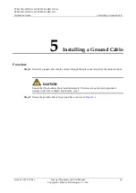
4
Installing Cabinets
4.1 Unpacking and Acceptance
Procedure
Step 1
Check whether the packing cases are intact. If a packing case is severely damaged or wet,
identify the cause and report the issue to your local Huawei office.
Step 2
Unpack the cases.
Step 3
Check the quantity of components against the packing lists attached to the packing cases. If
the quantity differs from that specified on the packing lists, identify the cause and report the
issue to your local Huawei office.
----End
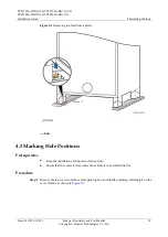
4.2 Removing the Cabinet from the Pallet
Procedure
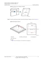
Step 1
Remove the bolts that secure the cabinet to the pallet.
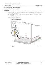
Step 2
Remove the cabinet from the pallet.


