TP48120A-HD15A1, TP48120A-HD15A2,
TP48200A-HD15A1, and TP48200A-HD15A2 Telecom
Power
User Manual
4 Maintenance
Issue 03 (2020-01-04)
Copyright © Huawei Technologies Co., Ltd.
53
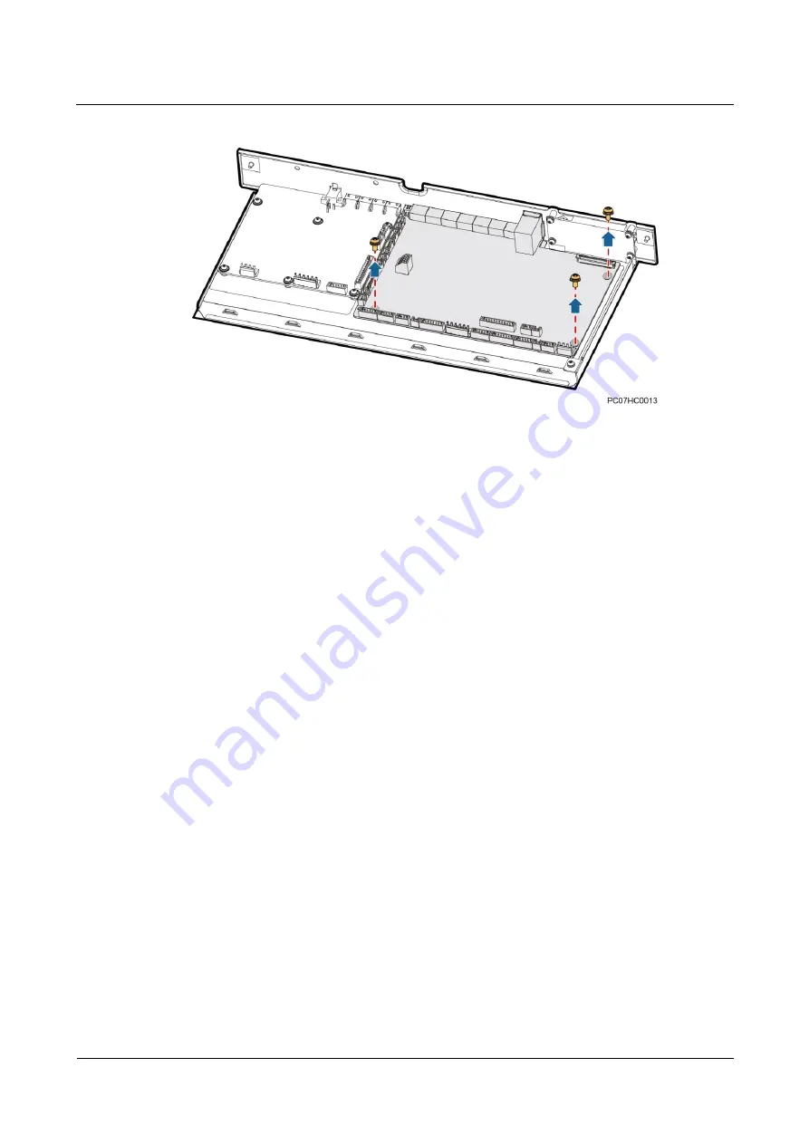
Figure 4-6
Removing the main control board
Step 10
Place the new main control board, and tighten the screws for it.
Step 11
Install the LCD flat cable.
1.
Insert the LCD flat cable into the connector levelly and gently.
2.
Press the latch lock on the connector to lock the LCD flat cable.
Step 12
Connect the cables to the input ports on the new main control board.
Step 13
Reinstall the cover on the main monitoring board.
Step 14
Insert the SMU06C, and tighten the screws.
Step 15
Connect the signal cable to the SMU06C based on the recorded information.
Step 16
Flip the battery switch back to AUTO.
Step 17
Set SMU parameters again.
Step 18
Disconnect the ground cable from the ESD wrist strap, and take off the ESD wrist strap and
ESD gloves.
----End
Follow-up Procedure
Pack the removed component, and return it to Huawei local warehouse.
4.4.3 Installing the SMU06C Fan Extended Board
Prerequisites
You have obtained an ESD wrist strap, a pair of ESD gloves, an ESD box or bag, the
cabinet door key, and tools.
The new fan extended board is intact. Do not reversely connect cables to the ports for
internal and external circulation fans.


