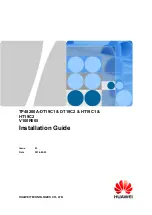
background image


TP48200A-DT19C1 & DT19C2 & HT19C1 & 
HT19C2


V100R005


Installation Guide


Issue 

03


Date 

2014-02-23


HUAWEI TECHNOLOGIES CO., LTD. 

Summary of Contents for Telecom Power TP48200A-DT19C1

Page 1: ...TP48200A DT19C1 DT19C2 HT19C1 HT19C2 V100R005 Installation Guide Issue 03 Date 2014 02 23 HUAWEI TECHNOLOGIES CO LTD ...

Page 2: ...ei and the customer All or part of the products services and features described in this document may not be within the purchase scope or the usage scope Unless otherwise specified in the contract all statements information and recommendations in this document are provided AS IS without warranties guarantees or representations of any kind either express or implied The information in this document i...

Page 3: ... Symbol Description Indicates an imminently hazardous situation which if not avoided will result in death or serious injury Indicates a potentially hazardous situation which if not avoided could result in death or serious injury Indicates a potentially hazardous situation which if not avoided may result in minor or moderate injury Indicates a potentially hazardous situation which if not avoided co...

Page 4: ...ry Changes between document issues are cumulative The latest document issue contains all the changes made in earlier issues Issue 03 2014 02 23 Optimized the content of the document Issue 02 2013 11 06 Optimized the content of the document including standardizing the terminology and improving the accuracy of the description Issue 01 2013 08 06 This issue is the first official release ...

Page 5: ...pment Safety 9 1 2 1 Electricity Safety 9 1 2 2 Electrostatic Discharge 10 1 2 3 Laying Out Cables 10 1 2 4 Rectifier 10 2 Installation Preparations 11 2 1 Required Tools 11 2 2 Technical Specifications 12 2 3 Installation Dimensions 13 2 4 Requirements for Cable Routing 13 3 Components 16 3 1 Interior 16 3 2 Rectifier 22 3 3 SMU02B 23 3 4 UIM02C 27 3 5 Sensor 30 3 5 1 Optional Smoke Sensor 33 3 5...

Page 6: ...tional Installing an Ambient Temperature and Humidity Sensor 55 7 Installing Cables 58 7 1 Optional Installing Dry Contact Signal Cables 58 7 2 Installing the Communications Cables 59 7 2 1 WebUI Management 59 7 2 2 NetEco Management 59 7 2 3 Third Party NMS Management over SNMP 60 7 2 4 Connecting to Huawei BBU over Dry Contacts M2000 Management 61 7 3 Installing DC Output Power Cables 63 7 4 Ins...

Page 7: ...arameters 83 10 6 Setting Sensor Parameters 84 10 7 Optional Setting Hibernation Parameters 85 10 8 Setting Communications Parameters 85 10 8 1 Setting Parameters Before Using WebUI Management 85 10 8 2 Optional Setting Parameters Before Using the NetEco Management 86 10 8 3 Setting Parameters Before Using the SNMP Management 87 10 9 Connecting the Battery Supply 90 10 10 Subsequent Operations 91 ...

Page 8: ...n addition to following the general precautions in this document follow the specific safety instructions given by Huawei Only trained and qualified personnel are allowed to install operate and maintain Huawei equipment This product should be used in the environment that meets design specifications Otherwise the product may be damaged and the resulting product exceptions or component damage are bey...

Page 9: ...TT or IT power system For DC supplied models Reinforced insulation or double insulation must be provided to isolate the DC source from the AC mains supply For DC supplied model The device applies to DC power source that complies with the Safety Extra Low Voltage SELV requirements in IEC 60950 1 based safety standards Prepared conductors are connected to the terminal block and only the appropriate ...

Page 10: ...AC power supply facility follow the local safety regulations The personnel who install the AC facility must be qualified to perform high voltage and AC operations Do not wear conductive articles such as watches hand chains bracelets and rings during the operation When water is found in the rack or the rack is damp switch off the power supply immediately When the operation is performed in a damp en...

Page 11: ...re powering it on 1 1 3 Inflammable Environment Operating the electrical device in an inflammable environment can be fatal Do not place the device in an environment that has inflammable and explosive air or gas Do not perform any operation in this environment 1 1 4 Battery Storage Battery Before operating storage batteries carefully read the safety precautions for battery handling and connection I...

Page 12: ...ectrolyte overflow When handling a storage battery ensure that its electrodes are upward Leaning or reversing the storage battery is prohibited Do not wear metal articles such as wristwatch hand chain bracelet and ring Short Circuit Battery short circuit may cause human injuries Although the voltage of ordinary batteries is low the instantaneous high current caused by the short circuit releases a ...

Page 13: ... the temperature of the battery is higher than 60 C check the battery for electrolyte overflow If the electrolyte overflows absorb and counteract the electrolyte immediately Battery Leakage If the electrolyte overflows absorb and counteract the electrolyte immediately When moving or handling a battery whose electrolyte leaks note that the leaking electrolyte may hurt human bodies When you find the...

Page 14: ...lities are in good condition Hoisting Heavy Objects Do not walk below the cantilever or hoisted objects when heavy objects are being hoisted Only trained and qualified personnel can perform hoisting operations Before hoisting heavy objects check that the hoisting tools are complete and in good condition Before hoisting heavy objects ensure that the hoisting tools are fixed to a secure object or wa...

Page 15: ...e two long sides To minimize the risk of falling hold your balance on the ladder before any operation Do not climb higher than the fourth rung of the ladder counted from up to down If you want to climb up a roof ensure that the ladder top is at least one meter higher than the roof 1 1 6 Mechanical Safety Drilling Holes Do not drill the cabinet at will Drilling holes without complying with the requ...

Page 16: ...ols in a safe place Otherwise if any of them fall into the operating fans the fans may be damaged When replacing a component near fans do not insert your fingers or boards into the operating fans until the fans are switched off and stops running Lifting Heavy Objects When heavy objects are being lifted do not stand or walk under the cantilever or the lifted object 1 1 7 Bundling Signal Cables Do n...

Page 17: ...damaged by the static on human bodies you must wear a well grounded electrostatic discharge ESD wrist strap when touching the device or handling boards or application specific integrated circuits ASICs 1 2 3 Laying Out Cables When the temperature is very low violent strike or vibration may damage the cable sheathing To ensure safety comply with the following requirements Cables can be laid or inst...

Page 18: ...allation Preparations Issue 03 2014 02 23 Huawei Proprietary and Confidential Copyright Huawei Technologies Co Ltd 11 2 Installation Preparations 2 1 Required Tools Figure 2 1 lists the tools that are required for the installation Use tools with insulated handles ...

Page 19: ...nologies Co Ltd 12 Figure 2 1 Installation tools 2 2 Technical Specifications Table 2 1 Technical specifications Model Dimensions H x W x D Weight Cabinet TP48200A DT19C1 2030 mm x 820 mm x 760 mm including the 150 mm high base and excluding the protruding part of the door 200 kg excluding rectifiers and batteries TP48200A DT19C2 TP48200A HT19C1 TP48200A HT19C2 ...

Page 20: ...ea preventing direct damage melting to the insulation layer or functional degradation aging or broken The bending radius of cables should be greater than or equal to five times the diameter of the cables Cables of the same type should be bound together Cables of different types should keep a minimum distance of 30 mm from each other to avoid tangles Cables that are bound together should be close t...

Page 21: ...d in a power cable In case of insufficient cable length use a longer cable Cable Hole Distribution Figure 2 3 shows the distribution of the cable holes on the partition plate Figure 2 3 Distribution of the cable holes on the partition plate 1 Temperature and humidity sensor cable 2 AC cables reserved 3 AC input cables 4 Sensor battery or DC power cables 5 DC cables reserved Figure 2 4 shows the di...

Page 22: ...Guide 2 Installation Preparations Issue 03 2014 02 23 Huawei Proprietary and Confidential Copyright Huawei Technologies Co Ltd 15 Figure 2 4 Distribution of the cable holes on the bottom plate 1 AC cables reserved 2 AC input cables 3 DC cables reserved ...

Page 23: ...19C1 HT19C2 Installation Guide 3 Components Issue 03 2014 02 23 Huawei Proprietary and Confidential Copyright Huawei Technologies Co Ltd 16 3 Components 3 1 Interior TP48200A DT19C1 Figure 3 1 shows the TP48200A DT19C1 interior ...

Page 24: ...ntenance socket 3 Air filter 4 Optional Electric door lock 5 Optional Bluetooth controller 6 TCUA control box 7 Thermoelectric cooler TEC 8 Space for installing batteries 9 Space for installing customer equipment 10 Space for installing rectifiers 11 User interface module UIM 12 DC power distribution unit PDU 13 Site monitoring unit SMU 14 AC input circuit breaker 15 Fan assembly 16 Battery switch...

Page 25: ...P48200A DT19C2 interior Figure 3 2 TP48200A DT19C2 interior 1 Optional Intelligent electric meter 2 Optional Maintenance socket 3 Air filter 4 Optional Electric door lock 5 Optional Bluetooth controller 6 TCUA control box 7 TEC 8 Space for installing batteries 9 Space for installing customer equipment 10 Space for installing rectifiers 11 UIM 12 DC PDU 13 SMU 14 AC input circuit breaker 15 Fan ass...

Page 26: ...s Co Ltd 19 16 Battery switch 17 Cabinet ground bar 18 Optional Current transformer TP48200A HT19C1 Figure 3 3 shows the TP48200A HT19C1 interior Figure 3 3 TP48200A HT19C1 interior 1 Optional Intelligent electric meter 2 Optional Maintenance socket 3 Heat exchanger HXC70S 4 Optional Bluetooth controller 5 Optional Electric door lock 6 TCUA control box ...

Page 27: ...ht Huawei Technologies Co Ltd 20 7 TEC 8 Space for installing batteries 9 Space for installing customer equipment 10 Space for installing rectifiers 11 UIM 12 SMU 13 DC PDU 14 AC input circuit breaker 15 Battery switch 16 Cabinet ground bar 17 Optional Current transformer TP48200A HT19C2 Figure 3 4 shows the TP48200A HT19C2 interior ...

Page 28: ...ional Intelligent electric meter 2 Optional Maintenance socket 3 Heat exchanger HXC70S 4 Optional Bluetooth controller 5 Optional Electric door lock 6 TCUA control box 7 TEC 8 Space for installing batteries 9 Space for installing customer equipment 10 Space for installing rectifiers 11 UIM 12 SMU 13 DC PDU 14 AC input circuit breaker 15 Battery switch 16 Cabinet ground bar 17 Optional Current tran...

Page 29: ...or Status Description Power indicator Green Steady on The rectifier has an AC power input Off The rectifier has no AC power input The rectifier is faulty Blinking at 0 5 Hz The rectifier is being queried Blinking at 4 Hz The rectifier is loading an application program Alarm indicator Yellow Off No alarm is generated Steady on The rectifier generates an alarm for power limiting due to ambient overt...

Page 30: ...The rectifier is hibernating Blinking at 0 5 Hz The communication between the rectifier and the SMU is interrupted Fault indicator Red Off The rectifier is running properly Steady on The rectifier locks out due to output overvoltage The rectifier has no output due to an internal fault 3 3 SMU02B Appearance Figure 3 6 shows an SMU02B Figure 3 6 SMU02B appearance Panel Figure 3 7 shows an SMU02B pan...

Page 31: ... Indicators Table 3 2 describes the indicators on the SMU02B panel Table 3 2 SMU02B indicator description Name Color Status Description Run indicator Green Off The SMU is faulty or has no DC input Blinking at 0 5 Hz The SMU is running properly and communicating with the host properly Blinking at 4 Hz The SMU is running properly but is not communicating with the host properly Minor alarm indicator ...

Page 32: ...kly adjust values Back Returns to the previous menu without saving the settings Confirm Enters the main menu from the standby screen Enters a submenu from the main menu Saves the menu settings Communication Ports Table 3 4 describes the communication ports on the SMU02B panel Table 3 4 SMU02B communication port description Communication Port Communications Parameter Communications Protocol Functio...

Page 33: ...85 RS232 port Table 3 5 Pin definitions for the FE port Pin Signal Description 1 TX Sends data over FE 2 TX 3 RX Receives data over FE 6 RX 4 5 7 and 8 None N A Table 3 6 Pin definitions for the RS485 RS232 port Pin Signal Description 1 TX Sends data over RS485 2 TX 4 RX Receives data over RS485 5 RX 3 RX232 Receives data over RS232 7 TX232 Sends data over RS232 6 PGND Connects to the ground 8 Non...

Page 34: ...eter inputs including one ambient temperature and humidity input two ambient temperature inputs and one battery temperature input Figure 3 9 shows a UIM02C panel Figure 3 9 UIM02C panel Ports Table 3 7 UIM02C ports Port Type Silk Screen Description Sensor ports TEM HUM Ambient temperature and humidity sensor WATER Water sensor TEMP1 Ambient temperature sensor 1 TEMP2 Ambient temperature sensor 2 G...

Page 35: ...ut ports and alarms see the appendix ALM2 ALM3 ALM4 ALM5 ALM6 ALM7 ALM8 Communications port COM RS485 port Communication Port Table 3 8 COM communication port description Communication Port Communications Parameter Communications Protocol Function COM port Baud rate 9600 bit s 19200 bit s M S and Modbus protocol Connects to lower level devices such as the battery voltage detector DC Air Conditione...

Page 36: ...r the COM port Pin Signal Description 1 RX Receives data over RS485 2 RX 4 TX Sends data over RS485 5 TX 6 PGND Connects to the ground 3 7 8 None N A Pins Figure 3 11 shows the pin numbers of the sensor ports Table 3 10 defines the pins Figure 3 11 UIM02C pin numbers Table 3 10 UIM02C pin definitions Silkscreen No Pin Definitions TEM HUM 1 12 V 2 ENV_TEMP 3 12 V 4 ENV_HUM WATER 1 12 V 2 WATER ...

Page 37: ...ght Huawei Technologies Co Ltd 30 Silkscreen No Pin Definitions 3 GND 4 Not defined TEMP1 1 GND 2 TEMP1 TEMP2 1 GND 2 TEMP2 GATE 1 GATE 2 GATE SMOKE 1 SMOKE 2 12 V BTEMP 1 GND 2 BTEMP 3 5 Sensor Figure 3 12 shows the positions of all sensors in the TP48200A DT19C1 DT19C2 while Figure 3 13 shows those for the TP48200A HT19C1 HT19C2 ...

Page 38: ...etary and Confidential Copyright Huawei Technologies Co Ltd 31 Figure 3 12 Sensors TP48200A DT19C1 DT19C2 1 Optional Ambient temperature and humidity sensor 2 Door status sensor 3 Optional Smoke sensor 4 Temperature sensor in the equipment compartment 5 Battery temperature sensor 6 Optional Water sensor ...

Page 39: ...etary and Confidential Copyright Huawei Technologies Co Ltd 32 Figure 3 13 Sensors TP48200A HT19C1 HT19C2 1 Optional Ambient temperature and humidity sensor 2 Door status sensor 3 Temperature sensor in the equipment compartment 4 Optional Smoke sensor 5 Battery temperature sensor 6 Optional Water sensor ...

Page 40: ... 3 Components Issue 03 2014 02 23 Huawei Proprietary and Confidential Copyright Huawei Technologies Co Ltd 33 3 5 1 Optional Smoke Sensor Figure 3 14 Smoke sensor 1 1 Wiring port 2 Base 3 Indicator Figure 3 15 Smoke sensor 2 1 Wiring port 2 Base 3 Indicator ...

Page 41: ...uide 3 Components Issue 03 2014 02 23 Huawei Proprietary and Confidential Copyright Huawei Technologies Co Ltd 34 3 5 2 Optional Temperature and Humidity Sensor Figure 3 16 Temperature and humidity sensor 1 Figure 3 17 Temperature and humidity sensor 2 ...

Page 42: ...Figure 3 19 Battery temperature sensor 3 5 5 Temperature Sensor in the Equipment Compartment Figure 3 19 shows the temperature sensor in the equipment compartment 3 6 Optional Intelligent Electric Meter An intelligent electric meter works together with a current transformer and can measure the AC current voltage frequency power factor active power and total power and facilitates automatic manageme...

Page 43: ...l Copyright Huawei Technologies Co Ltd 36 Appearance and Pin Definitions Figure 3 20 Appearance of the current transformer Figure 3 21 Appearance and pins of the intelligent electric meter Table 3 11 Pin definitions of the intelligent electric meter Pin Definitions 1 2 Power supply 3 4 RS485 communication 5 Phase A voltage ...

Page 44: ... Phase C voltage 8 Neutral wire 10 Current transformer port 3 7 Optional Bluetooth Door Lock The Bluetooth door lock consists of the electric door lock and Bluetooth controller which is used to control the electric door lock 3 7 1 Optional Electric Door Lock Appearance Figure 3 22 shows an electric door lock Figure 3 22 Electric door lock Port Definitions Figure 3 23 Ports on the electric door loc...

Page 45: ... Ltd 38 Table 3 12 Port definitions of the electric door lock Pin Definitions Description 1 TX Sends data over RS485 2 TX 3 12 V Supplies power for the electric door lock 4 RX Receives data over RS485 5 RX 6 OPEN_DOOR Controls the electric door lock reserved 7 GND GND 8 GND GND 3 7 2 Optional Bluetooth Controller Appearance Figure 3 24 Bluetooth controller ...

Page 46: ...the Bluetooth controller Pin Definitions 1 AC input 2 AC input 3 Connects to pin 4 4 Connects to pin 3 5 12 V 6 12 V 7 Controls the electric door lock 8 Controls the electric door lock 9 3 8 Optional Battery Storage batteries store electrical energy and power loads when the D G and mains supply no power or insufficient power The cabinet can be configured with two 150 Ah lead acid batteries The max...

Page 47: ...s severely damaged or wet identify the cause and report the issue to your local Huawei office Step 2 Unpack the cases Step 3 Check the quantity of components against the packing lists attached to the packing cases If the quantity differs from that specified on the packing lists identify the cause and report the issue to your local Huawei office End 4 2 Removing a Cabinet from a Pallet Procedure St...

Page 48: ...cabinet from the pallet 1 Pallet Figures of the cabinet and the pallet are for reference only End 4 3 Marking Hole Positions Prerequisites The installation environment is clean and dry The concrete pad on which the cabinet is to be installed is flat Procedure Step 1 Remove the cover from the cabinet packing box and locate the hole marking off template on the cover interior as shown in Figure 4 2 ...

Page 49: ... positions based on the marking off template as shown in Figure 4 3 Figure 4 3 Marking mounting holes for the cabinet 1 Marker 2 Marking off template 3 Mounting holes 4 Concrete floor End 4 4 Drilling Holes and Installing Expansion Sleeves Procedure Step 1 Drill holes to a depth of 52 mm to 60 mm using a hammer drill Step 2 Partially tighten each expansion bolt place it vertically into the hole an...

Page 50: ...her 3 Flat washer 4 Expansion sleeve 5 Expansion nut 6 Concrete floor End 4 5 Hoisting and Installing the Cabinet Context Install the cabinet based on site requirements The maximum weight of the cabinet is 200 kg excluding batteries and rectifiers For safety ropes used to carry the cabinet should be able to bear a weight greater than 600 kg triple the maximum weight of the cabinet Procedure Step 1...

Page 51: ...lling Cabinets Issue 03 2014 02 23 Huawei Proprietary and Confidential Copyright Huawei Technologies Co Ltd 44 Figure 4 5 Installing lifting eyes Step 3 Bind ropes through the lifting eyes and then hoist the cabinet to an appropriate position as shown in Figure 4 6 ...

Page 52: ...nstallation Guide 4 Installing Cabinets Issue 03 2014 02 23 Huawei Proprietary and Confidential Copyright Huawei Technologies Co Ltd 45 Figure 4 6 Hoisting the cabinet Step 4 Remove the ropes and lifting eyes Step 5 Reinstall the screws End ...

Page 53: ...pyright Huawei Technologies Co Ltd 46 4 6 Securing a Cabinet Procedure Step 1 Place the flat washers spring washers and expansion bolts into the mounting holes of the cabinet Step 2 Secure the expansion bolts Figure 4 7 Securing a cabinet End 4 7 Open the Cabinet Door Procedure Step 1 Loosen the screw on the door lock by using a hex key ...

Page 54: ...23 Huawei Proprietary and Confidential Copyright Huawei Technologies Co Ltd 47 Figure 4 8 Loosen screws Step 2 Rotate the protective cover on the door lock to expose the key hole Step 3 Insert the key into the key hole and rotate it clockwise and lift the small handle on the lower end of the lock ...

Page 55: ...4 Installing Cabinets Issue 03 2014 02 23 Huawei Proprietary and Confidential Copyright Huawei Technologies Co Ltd 48 Figure 4 9 Unlocking Step 4 Lift the handle and then rotate it rightwards to open the cabinet door Figure 4 10 Opening the cabinet door End ...

Page 56: ...2014 02 23 Huawei Proprietary and Confidential Copyright Huawei Technologies Co Ltd 49 5 Installing a Ground Cable Procedure Step 1 Route the ground cable into the cabinet through the hole at the left bottom of the cabinet Step 2 Secure the ground cable to the ground bar as shown in Figure 5 1 ...

Page 57: ... HT19C2 Installation Guide 5 Installing a Ground Cable Issue 03 2014 02 23 Huawei Proprietary and Confidential Copyright Huawei Technologies Co Ltd 50 Figure 5 1 Installing a ground cable 1 Cabinet ground bar 2 Site ground bar End ...

Page 58: ...ller panel is removed from the slot where you will install a rectifier Do not put your hands into rectifier slots avoiding electric shocks When a rectifier is running a high temperature is generated around the air exhaust vent at the rear Do not touch the vent or cover the vent with cables or other objects Procedure Step 1 Push the locking latch towards the left Step 2 Draw the handle downwards St...

Page 59: ...logies Co Ltd 52 Figure 6 1 Installing a rectifier End 6 2 Optional Installing a Smoke Sensor Procedure Step 1 Locate the smoker sensor fastener inside the cabinet top Step 2 Install the smoke sensor base onto the fastener Ensure that the switch on the smoker sensor base faces the cabinet door Step 3 Secure the smoke sensor to the base as shown in Figure 6 2 ...

Page 60: ...i Proprietary and Confidential Copyright Huawei Technologies Co Ltd 53 Figure 6 2 Installing a smoke sensor Step 4 Connect one end of the signal cable to the smoke sensor and the other end to the SMOKE port on the UIM panel as shown in Figure 6 3 Figure 6 3 Connecting the signal cable for the smoke sensor ...

Page 61: ... Water Sensor Procedure Step 1 Put the water sensor into the right bottom of the cabinet and secure it with a cable tie as shown in Figure 6 4 When you install a water sensor ensure that the sensor hangs vertically and is 5 10 mm away from the cabinet bottom Figure 6 4 Installing a water sensor Step 2 Connect the signal cable for the water sensor to the WATER port on the UIM panel as shown in Figu...

Page 62: ...logies Co Ltd 55 Figure 6 5 Connecting the signal cable for the water sensor End 6 4 Optional Installing an Ambient Temperature and Humidity Sensor Procedure Step 1 Open the cover of the ambient temperature and humidity sensor Step 2 Connect one end of the signal cable to the sensor and the other end to the TEM HUM port on the UIM panel as shown in Figure 6 6 ...

Page 63: ...ary and Confidential Copyright Huawei Technologies Co Ltd 56 Figure 6 6 Connecting the signal cable for the ambient temperature and humidity sensor Step 3 Locate the fastener for the ambient temperature and humidity sensor in the left of the cabinet Step 4 Install the sensor onto the fastener as shown in Figure 6 7 ...

Page 64: ...tary and Confidential Copyright Huawei Technologies Co Ltd 57 Figure 6 7 Installing an ambient temperature and humidity sensor Number of screws varies as types of ambient temperature and humidity sensors differ Install the screws as required Step 5 Close the cover of the ambient temperature and humidity sensor End ...

Page 65: ...ch all the circuit breakers to OFF and remove the fuses from positions where cables will be installed 7 1 Optional Installing Dry Contact Signal Cables Procedure Step 1 Press the contact plate using a flat head screwdriver to flip the metal spring inside each dry contact Step 2 Connect the signal cables to the corresponding dry contacts Step 3 Put away the flat head screwdriver and check that the ...

Page 66: ...s 7 2 1 WebUI Management Procedure Step 1 Connect the FE port on the SMU by using a network cable as shown in Figure 7 2 Figure 7 2 Connecting a communications cable for WebUI management 1 FE port End 7 2 2 NetEco Management Networking Mode 1 over FE Port Step 1 Connect the FE port on the SMU by using a network cable as shown in Figure 7 3 Figure 7 3 Connecting a communications cable over the FE p...

Page 67: ...he network cable to the RS485 RS232 port on the SMU Step 2 Connect the other end to the MON1 port on the BBU as shown in Figure 7 4 Figure 7 4 Connecting a communications cable over the RS485 port 1 RS485 RS232 port 2 MON1 port End 7 2 3 Third Party NMS Management over SNMP Procedure Step 1 Connect the FE port on the SMU by using a network cable as shown in Figure 7 5 Figure 7 5 Connecting a commu...

Page 68: ...3 Huawei Proprietary and Confidential Copyright Huawei Technologies Co Ltd 61 End 7 2 4 Connecting to Huawei BBU over Dry Contacts M2000 Management Procedure Step 1 Alarm signals are sent over dry contacts Connect the dry contact signal cable to the EXT ALM port on the BBU as shown in Figure 7 6 ...

Page 69: ...t Huawei Technologies Co Ltd 62 Figure 7 6 Connecting the UIM02C and the BBU 1 BBU 2 EXT ALM1 port 3 EXT ALM0 port In the SRAN site based on the BSC6900 the external alarm port number scope of the two slots is 0 to 7 In the non SRAN site based on the BSC6900 the scope is 0 to 15 In the non SRAN site based on the BSC6000 the scope is 1 to 16 ...

Page 70: ...itch off all circuit breakers before installing power cables Procedure Step 1 Remove the front panel and top epoxy board from the PDU Step 2 Lay out the DC output cables along the cable ties on the cabinet side Step 3 Secure the negative DC output power cable to the corresponding DC output circuit breaker based on the actual load power Step 4 Secure the positive DC output power cable to the corres...

Page 71: ... cables 1 Load End 7 4 Installing AC Input Power Cables If an AC meter and a current transformer are configured route the AC input power cables through the current transformer first and then connect them to the AC input circuit breaker If a 110 V AC dual live wire L1 and L2 input power grid is met in this case after installing the AC input power cables you need to change the cable connection for t...

Page 72: ...in which an AC meter a current transformer and a maintenance socket are configured 7 4 1 Installing AC Input Power Cables for the TP48200A DT19C1 or TP48200A HT19C1 The following two input systems are supported 220 380 V AC three phase four wire input system and 220 V AC single phase input system Install AC input power cables based on the actual input system Installing Three Phase Four Wire AC Inp...

Page 73: ...rietary and Confidential Copyright Huawei Technologies Co Ltd 66 Figure 7 8 Installing 220 380 VAC three phase four wire input power cables 1 Alternating current distribution box ACDB End Installing 220 V AC Single Phase Input Power Cables Prerequisites Take the short circuit copper bar from the fitting bag ...

Page 74: ...nstalling the AC input power cables Step 2 Secure the copper bar to the AC circuit breaker Step 3 Route the 220 V AC single phase input power cables into the cabinet through the hole at the left bottom of the cabinet Step 4 Route AC input live wire L through hole A of the current transformer Step 5 Connect the live wire to the corresponding terminal screw on the short circuit copper bar Step 6 Con...

Page 75: ...HT19C1 HT19C2 Installation Guide 7 Installing Cables Issue 03 2014 02 23 Huawei Proprietary and Confidential Copyright Huawei Technologies Co Ltd 68 Figure 7 9 Installing 220 VAC single phase AC input power cables 1 ACDB End ...

Page 76: ...48200A HT19C2 Installing Cables for a 110 V AC Dual Live Wire System L1 L2 N Procedure Step 1 Route the 110 V AC power cables into the cabinet through the holes at the left bottom of the cabinet Step 2 Route live wires L1 and L2 through the current transformer Route L1 through hole A on the current transformer and L2 through hole B Step 3 Secure the AC input power cable to the AC input circuit bre...

Page 77: ...7 10 Installing cables for a 110 VAC dual live wire system L1 L2 N 1 ACDB End Installing 110 V AC Dual Live Wire Input Power Cables L1 and L2 Installing 110 V AC Dual live Wire Input Power Cables Step 1 Route the 110 V AC power cables into the cabinet through the holes at the left bottom of the cabinet Step 2 Route AC input live wire L1 through hole A of the current transformer ...

Page 78: ...d 71 Step 3 Secure the AC input power cables to the AC input circuit breaker as shown in Figure 7 11 Figure 7 11 Installing cables for a 110 VAC dual live wire system 1 ACDB End Changing the Cable Connection for the Intelligent Electric Meter Step 1 Remove the cover from the intelligent electric meter Step 2 Remove the voltage detection wiring terminal from the meter ...

Page 79: ...Installation Guide 7 Installing Cables Issue 03 2014 02 23 Huawei Proprietary and Confidential Copyright Huawei Technologies Co Ltd 72 Figure 7 12 Removing the wiring terminal Step 3 Remove the cables from Uc and Un and insulate the cables ...

Page 80: ... Step 4 Take the short circuit cables from the fitting bag and install them onto the Ub Uc and Un Figure 7 14 Installing the short circuit cables Step 5 Reinstall the voltage detection wiring terminal for the intelligent electric meter Step 6 Reinstall the cover for the meter End Changing the Cable Connection for the Maintenance Socket Step 1 Remove the protective cover from the maintenance socket...

Page 81: ...m the residual current device RCD Step 3 Remove AC input live wire L1 from the UT terminal Step 4 Connect the removed neutral wire to the position where L1 connects to the UT terminal and connect the removed L1 to the position where the neutral wire connects to the RCD Figure 7 15 Changing the cable connection for the maintenance socket Step 5 Reinstall the protective cover for the maintenance soc...

Page 82: ...ery acid contacts skin or clothing wash with soap and water immediately Do not use metal to simultaneously contact two or more battery terminals Do not use metal to simultaneously touch battery terminals and grounded objects for example battery compartment otherwise transient short circuit occurs which produces sparks or explosion During battery installation never short circuit or reversely connec...

Page 83: ...wei Technologies Co Ltd 76 Figure 8 1 Battery installation completed 8 1 Installing Battery Strings Prerequisites Ensure that batteries are from the same manufacturer and of the same model and have a close voltage New and old batteries cannot be used together Procedure Step 1 Install batteries into the battery compartment in the sequence shown in Figure 8 2 ...

Page 84: ...and Confidential Copyright Huawei Technologies Co Ltd 77 Figure 8 2 Installing battery strings End 8 2 Installing Copper Bars Between Batteries Procedure Step 1 Remove the insulation cover from the batteries Step 2 Install copper bars between batteries Step 3 Reinstall the insulation covers onto the two batteries in the middle ...

Page 85: ...uisites When installing battery cables install the negative cable before the positive cable Procedure Step 1 Take the negative battery cable from the left side of the battery compartment and install the cable to the negative battery wiring terminal Step 2 Take the positive battery cable from the right side of the battery compartment and install the cable to the positive battery wiring terminal Ste...

Page 86: ...19C1 DT19C2 HT19C1 HT19C2 Installation Guide 8 Optional Installing Batteries Issue 03 2014 02 23 Huawei Proprietary and Confidential Copyright Huawei Technologies Co Ltd 79 Figure 8 4 Installing battery cables End ...

Page 87: ...nnections Check that all circuit breakers or fuses are OFF Check that flat washers and spring washers are securely installed for all OT terminals and that all the OT terminals are intact and properly connected Check that batteries are correctly installed and that battery cables are correctly connected and not short circuited Check that input and output power cables and ground cables are correctly ...

Page 88: ...the status of the related unit or component meets requirements before turning on any switch When you are performing operations and do not want others to operate attach the label Do not turn on the switch because operations are in process to the power distribution device During commissioning shut down the device immediately if any fault is detected Rectify the fault and proceed with the commissioni...

Page 89: ...ed within 30 seconds You need to log in again if no button is pressed within 1 minute The preset password is 000001 Set the date and time as required Table 10 1 Setting the date and time Main Menu Second Level Menu Third Level Menu Default Value Setting Value Setting Wizard Date and Time NOTE The date and time vary according to time zones Set the time zone date and time based on the local situatio...

Page 90: ...T19C2 TP48200A HT19C2 Set to the local power supply input system NOTE If the local input system uses two live wires set the input system to Single Phase 10 5 Setting Battery Parameters Set the Battery1 Connected Battery2 Connected Rated Capacity and Installation Time as required Table 10 3 Setting battery parameters Main Menu Second Level Menu Third Level Menu Fourth Level Menu Default Value Setti...

Page 91: ...eries set Battery1 Connected and Battery2 Connected to Yes and others to No and set Rated Capacity to 150 Ah If battery route 1 is connected to two battery strings in parallel each battery string consists of four 12 V 150 Ah batteries in series set Battery1 Connected to Yes and others to No and set Rated Capacity to 300 Ah 10 6 Setting Sensor Parameters Set the sensor parameter to Yes or None base...

Page 92: ... the rectifiers Table 10 5 Setting hibernation parameters Main Menu Second Level Menu Third Level Menu Default Value Setting Value Parameters Settings Energy Saving Hibernation Enable No Yes 10 8 Setting Communications Parameters 10 8 1 Setting Parameters Before Using WebUI Management Procedure Step 1 Apply to the site or equipment room network administrator for a fixed IP address Step 2 Set the I...

Page 93: ...ubnet mask and gateway on the LCD as shown in Table 10 7 Table 10 7 IP parameters Main Menu Second Level Menu Third Level Menu Default Value Setting Setting Wizard Network Parameters IP Address 192 168 0 10 Set this parameter according to the IP address assigned by the network administrator Subnet Mask 255 255 255 0 Set this parameter according to the subnet mask provided by the network administra...

Page 94: ...l Menu Third Level Menu Fourth Level Menu Fifth Level Menu Default Value Setting Parameters Settings Comm Parameters Serial Port Northbound Port Mode Manual Manual Protocol Type M S Protocol M S Protocol M S Protocol Northbound Baud Rate 9600 9600 Comm Address 3 3 End 10 8 3 Setting Parameters Before Using the SNMP Management Prerequisites Before setting SNMP parameters obtain the information list...

Page 95: ...ddress subnet mask and gateway on the LCD as shown in Table 10 11 Table 10 11 IP parameters Main Menu Second Level Menu Third Level Menu Default Value Setting Setting Wizard Network Parameters IP Address 192 168 0 10 Set this parameter according to the IP address assigned by the network administrator Subnet Mask 255 255 255 0 Set this parameter according to the subnet mask provided by the network ...

Page 96: ...tab page select SNMP If the SNMP version is SNMPv1 or SNMPv2c set SNMP Version to SNMPv1 SNMPv2c under SNMP and then set SNMP Port Number Read Community Name and Write Community Name as shown in Figure 10 2 Figure 10 2 Setting SNMPv1 and SNMPv2c parameters If the SNMP version is SNMPv3 set SNMP Version to SNMPv3 under SNMP click Add under SNMPv3 and then set User Name MD5 Password and DES Password...

Page 97: ...e Mib file and import it to the NMS If there is only one NMS perform Step 6 once End Follow up Procedure You can query the power system operating status active alarms and the names of user defined dry contact inputs and configure dry contact outputs on the NMS that is connected over the SNMP 10 9 Connecting the Battery Supply Prerequisites To avoid damage to batteries switch on the battery circuit...

Page 98: ...ry switch is in the AUTO position by default before delivery and the system is under automatic control Open the cover and flip the battery switch to MANUAL only when you need to power on the battery forcibly Remember to flip the battery back to AUTO after the commissioning Figure 10 4 Battery switch 1 Battery switch behind the cover End 10 10 Subsequent Operations Procedure Step 1 Reinstall the re...

Page 99: ...put DIN1 Dry contact input 1 DIN2 Dry contact input 2 DIN3 Dry contact input 3 DIN4 Dry contact input 4 DIN5 Dry contact input 5 DIN6 TP48200A DT19C1 and TP48200A DT19C2 TEC Alarm TP48200A HT19C1 and TP48200A HT19C2 TCUA Alarm Dry contact output The default setting closed alarm open normal can be modified ALM1 Mains faults ALM2 DC overvoltage and undervoltage ALM3 Rectifier faults ALM4 AC surge pr...

Page 100: ... B Acronyms and Abbreviations B BBU baseband unit BLVD Battery low voltage disconnection H HTTPS Hypertext Transfer Protocol Secure L LLVD Load low voltage disconnection P PDU Power distribution unit S SMU Site monitoring unit SNMP Simple Network Management Protocol SPD Surge protection device T TCUA Temperature control unit A TEC Thermoelectric cooler U UIM User interface module ...

Reviews: