TP482000B V300R002C03 Telecom Power
(TP482000B-N20B1, TP482000B-N20B2,
TP481200B-N20B1, and TP481200B-N20B2)
User Manual
6 Routine Maintenance
Issue 07 (2020-04-10)
Copyright © Huawei Technologies Co., Ltd.
51
6.5 Parameters on the SMU
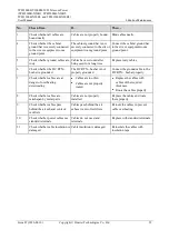
Table 6-5
SMU parameter maintenance
No.
Maintenance Item
If...
Then...
1
Check whether the displayed
battery capacity and number of
battery strings are the same as the
actual data.
Parameters are set
incorrectly.
The number of batteries is
changed, or batteries are
replaced.
Set battery parameters again.
2
Check
Charge Current Limit
Coefficient
. The value is
typically
0.10C10
and adjustable.
N/A
Change the value as required.
Otherwise, retain
0.10C10
.
3
Check whether the displayed
battery temperature is the same
as the actual temperature.
The battery temperature
sensor is faulty.
The SMU is faulty.
1.
Replace the battery
temperature sensor.
2.
Replace the SMU.
4
Check whether the displayed
total load current is the same as
the actual current measured by a
clamp meter.
The current monitoring cable
is loose.
The SMU is faulty.
1.
Check that the current
monitoring cable is securely
connected.
2.
Replace the SMU.
5
Check whether the displayed
battery charge current displayed
on the SMU is the same as the
actual current measured by a
clamp meter.
The current monitoring cable
is loose.
The SMU is faulty.
1.
Check that the current
monitoring cable is securely
connected.
2.
Replace the SMU.
6
Check whether the difference
between the displayed DC output
voltage and the measured DC
busbar voltage is less than ±0.5
V DC.
The cabinet busbar and
cables are loose or in poor
contact.
The SMU is faulty.
1.
Check and secure cabinet
busbar and cable connections.
2.
Replace the SMU.
6.6 Cables
Table 6-6
Cable maintenance checklist
No.
Check Item
If...
Then...
1
Check whether signal cables and
power cables are separately
bound.
Signal cables and power cables
are bound together.
Bind signal cables and power
cables separately.
2
Check whether cables are at least
20 mm away from DC negative
busbars, fuses, and shunts.
Cables are installed too close to
DC negative busbars, fuses, and
shunts.
Install cables at least 20 mm
away from DC negative busbars,
fuses, and shunts.

