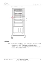


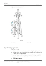


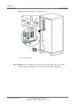


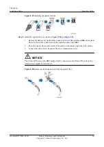


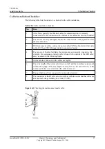
Figure 9-12
Securing the insulation cover to the short-circuiting copper bar
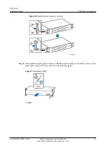
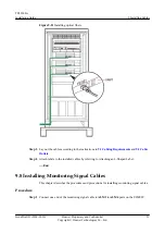
Step 6
Install the removed cover plate on the AC PDU.
Step 7
Lay out the cables according to the instructions in
and
Step 8
Label the installed cables according to the instructions in Attaching a Sign Plate Label.
----End
9.4 Installing BBU Equipotential Cables
A BBU equipotential cable connects ground bolts on a BBU and a TP48200A to ensure the
equipotential bonding between the BBU and TP48200A.
Context
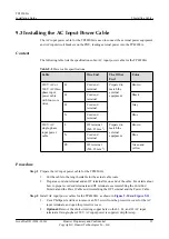
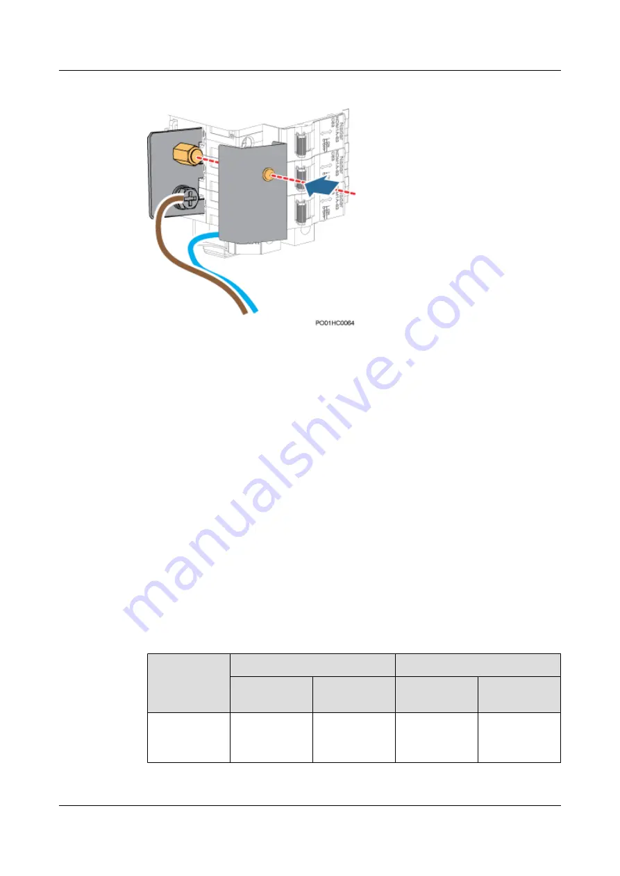
The following table lists the specifications of a BBU power cable.
Table 9-3
Specifications of a BBU power cable
Cable
One End
The Other End
Connector
Connected
to...
Connector
Connected
to...
BBU
equipotential
cable
OT terminal
(M4, 6 mm
2
)
BBU ground
screw
OT terminal
(M6, 6 mm
2
)
Ground screw in
the cabinet
TP48200A
Installation Guide
9 Installing Cables
Issue Draft B (2014-01-20)
Huawei Proprietary and Confidential
Copyright © Huawei Technologies Co., Ltd.
42


