background image


U8800 Maintenance Manual Basic Version V1.1 

Internal 


2011-03-21 

Huawei confidential. No spreading without permission. 

Page 3 of 61


Contents 

1


PRODUCT INTRODUCTION

......................................................................................................................................5


1.1


P

RODUCT 

A

PPEARANCE

.............................................................................................................................................5


1.2


P

RODUCT 

S

PECIFICATIONS

.........................................................................................................................................5


2


MAINTENANCE INSTRUCTIONS

............................................................................................................................7


2.1


D

OCUMENT 

A

PPLICATION

..........................................................................................................................................7


2.2


M

AINTENANCE 

P

RECAUTIONS

..................................................................................................................................7


2.3


M

AINTENANCE 

I

NFORMATION 

D

IRECTION

..............................................................................................................7


3


EXPLOSIVE VIEW OF THE WHOLE UNIT

..........................................................................................................8


4


LOCATION OF COMPONENTS ON THE MAIN BOARD

...............................................................................10


5


SOFTWARE UPGRADE

..............................................................................................................................................14


5.1


U

PGRADE 

P

REPARATION

..........................................................................................................................................14


5.2


N

ORMAL 

U

PGRADE 

P

ROCESS

..................................................................................................................................14


5.3


F

ORCE 

U

PGRADE 

P

ROCESS

......................................................................................................................................15


5.4


C

HECK 

F

IRMWARE 

V

ERSION

...................................................................................................................................17


5.5


E

RROR HANDLING

.....................................................................................................................................................17


6


MAINTENANCE TOOLS

............................................................................................................................................18


7


DISASSEMBLY PROCESS

.........................................................................................................................................20


8


ASSEMBLY PROCESS

.................................................................................................................................................26


9


TROUBLESHOOTING OF COMMON FAILURES

............................................................................................32


9.1


P

RINCIPLE 

I

NSTRUCTION

.........................................................................................................................................32


9.2


N

P

OWER ON

...........................................................................................................................................................33


9.2.1


No Power on---High current

.............................................................................................................................................33


9.2.2


No Power on--Small current

.............................................................................................................................................34


9.3


C

HARGE 

F

AILURE

......................................................................................................................................................36


9.4


LIGHT 

S

ENSOR 

F

AILURE

...........................................................................................................................................37


9.5


SIM


C

ARD 

F

AILURE

..................................................................................................................................................38


9.6


TF


C

ARD 

F

AILURE

....................................................................................................................................................39


9.7


D

ISPLAY 

F

AILURE

......................................................................................................................................................39


9.8


T

OUCH 

P

ANEL 

F

AILURE

............................................................................................................................................41


9.9


A

UDIO 

F

AILURE

.........................................................................................................................................................41


9.9.1


No Ring Tone

.........................................................................................................................................................................41


9.9.2


Voice Transmitting Failure

................................................................................................................................................44


9.9.3


Receiver Failure

....................................................................................................................................................................44


9.10


E

ARPHONE

&TV


OUT


F

AILURE

..............................................................................................................................45


9.11


C

AMERA 

F

AILURE

.....................................................................................................................................................46


9.12


V

IBRATION 

F

AILURE

.................................................................................................................................................47


9.13


WIFI


&BT


F

AILURE

..................................................................................................................................................48


9.14


GPS


F

AILURE

.............................................................................................................................................................49


9.15


A

CCELEROMETER 

&


E

LECTRONIC 

C

OMPASS 

F

AILURE

........................................................................................50


9.16


RF


R

ECEIVING 

F

AILURE

...........................................................................................................................................51


9.16.1


RF Receiving Failure-WCDMA900MHz

................................................................................................................51


9.16.2


RF Receiving Failure-WCDMA2100MHz

..............................................................................................................53


9.16.3


RF Receiving Failure-GSM850&900

.......................................................................................................................54


9.16.4


RF Receiving Failure-GSM1800&1900

...................................................................................................................54


9.17


RF


T

RANSMITTING 

F

AILURE

...................................................................................................................................56


9.17.1


RF Transmitting Failure-WCDMA900MHz

...........................................................................................................56


Summary of Contents for u8800

Page 1: ...U8800 Maintenance Manual Basic Version V1 1 Prepared by Product Department Documentation Team Date 2011 3 21 Reviewed by Date Approved by Date Huawei Technologies Co Ltd All rights reserved ...

Page 2: ...Huawei confidential No spreading without permission Page 2 of 61 Revision record Date Revision Version Revision Cause Section Number Change Description Author 2010 11 24 V1 0 Product Department Documentation Team 2011 3 21 V1 1 Product Department Documentation Team ...

Page 3: ...TROUBLESHOOTING OF COMMON FAILURES 32 9 1 PRINCIPLE INSTRUCTION 32 9 2 NO POWER ON 33 9 2 1 No Power on High current 33 9 2 2 No Power on Small current 34 9 3 CHARGE FAILURE 36 9 4 LIGHT SENSOR FAILURE 37 9 5 SIM CARD FAILURE 38 9 6 TF CARD FAILURE 39 9 7 DISPLAY FAILURE 39 9 8 TOUCH PANEL FAILURE 41 9 9 AUDIO FAILURE 41 9 9 1 No Ring Tone 41 9 9 2 Voice Transmitting Failure 44 9 9 3 Receiver Fail...

Page 4: ...n V1 1 Internal 2011 03 21 Huawei confidential No spreading without permission Page 4 of 61 9 17 2 RF Transmitting Failure WCDMA2100MHz 58 9 17 3 RF Transmitting Failure GSM 59 10 FUNCTIONAL TEST 60 10 1 MMI TEST 60 10 2 VOICE CALL TEST 61 ...

Page 5: ...W H 120mm L 62mm W 11 6mm T Weight 130g including the battery Power Supply 100 240V 50 60Hz Shape Bar type Antenna Built in antenna WCDMA HSDPA 3GPP FDD Release 99 Release 5 International standard 3GPP R5 GSM GPRS 3GPP R99 Technical Standards WCDMA 900 2100 MHz HSDPA 7 2Mbit s GSM GPRS EDGE 850 900 1800 1900 MHz WCDMA 2100MHz 1920 1980MHz 2110 2170MHz Uplink Downlink Frequency Band WCDMA 900MHz 88...

Page 6: ...G up to 440 hours 3G Headset interface 3 5mm USB interface USB2 0 High Speed 480Mbps External Memory support MicroSD Card up to 32GB Interface Standard 6 pin SIM card interface LCD Type TFT flat capacitive touch sensitive screen with 800 480 WVGA resolution Size 3 8 inches Display Screen Color 16M WCDMA HSDPA 900 2100MHz 24dBm Power Class 3 GSM GPRS850 MHz 900MHz 33dBm Power Class 4 Maximum transm...

Page 7: ...ted only by qualified technical personnel z Always wear an antistatic wrist strap during the operation and conduct the maintenance in an antistatic room z Ensure that all the components screws and insulators are properly installed after maintenance or calibration Ensure that all the cables are properly connected z Ensure that the soldering should comply with the environmental requirements and is l...

Page 8: ...exploded view is only applied to show phone frame It is not regarded as a reference for applying spare parts NO Description Quantity 1 Main_lens 1 2 Touch _lens 1 3 Front_cover_ASM 1 4 LCD_ASM 1 5 Metal_frame 1 6 MIC_Rubber 1 7 Sub_PCB 1 8 Volume_Key_DOME 1 9 Power_Key_DOME 1 10 Main_PCB 1 11 Mpcb_Foam 1 1 24 16 5 7 9 11 13 15 17 19 21 14 23 25 3 6 8 10 18 20 22 4 2 12 ...

Page 9: ...mission Page 9 of 61 NO Description Quantity 12 Back_cover_ASM 1 13 Coaxial cable 1 14 Screws_1 2 15 Camera _cover 1 16 Test_Hole_Rubber 1 17 Screws_2 4 18 TF_Sheet 1 19 Power_key 1 20 Product label_ Plastic_frame 1 21 Side_volum_key 1 22 Battery 1 23 Deco_Cover_Asm 1 24 BATTERY_COVER_ASM 1 25 Product label 1 ...

Page 10: ...failure U601 Color LED driver chip Failure symptom LED failure J202 FPC Connector Power key Failure symptom No power on U3301 TX Filter WCDMA900MHz Failure symptom RF transmitter failure X402 Crystal 32 768 KHz Failure symptom No power on U1701 FLASH Failure symptom No power on RF failure X701 Crystal 24 576KHz Failure symptom No power on U1201 LCD backlight Chip Module Failure symptom Backlight f...

Page 11: ...102 SAW Filter GPS Failure symptom GPS function failure U3603 LVCMOS Single GSM Failure symptom RF transmitter failure RF receiver failure U3701 WCMDA GSM Radio Transceiver Failure symptom RF transmitter failure RF receiver failure GPS failure U4201 BT WiFi Chip Failure symptom WiFi BT failure J1501 Battery Socket Failure symptom No power on Charge failure J1301 BTB Connector Failure symptom Voice...

Page 12: ...EBAND PROCESSOR MSM7230 Pb Free U201 39110468 Voltage Regulator U203 39200177 Power Management IC of QUALCOMM MSM7x30 Series PM8058 pb free U301 39110531 DCDC Control Chip 20pin U1001 39110504 Voltage Regulator 0 3 46V U1201 38140016 Semiconductor Sensor Accelerometer Electronic Compass Pb free U1401 47140032 RF Switch 824 960MHz 1710 2170MHz U3202 13010186 SAW Filter 1950MHz U3301 47100281 Power ...

Page 13: ...ght Male J703 14240229 Headphone Connector 3 5mm 6pins J801 22050053 MIC 44dB MIC301 15050014 NPN Triode 45V Q801 07040061 Varistor 12V 99999V RV301 RV302 32050026 Vibrator U502 38140017 semiconducting sensor light Proximity sensor U601 38020035 Analog Switch U801 39110523 LED Flash Driver IC QFN16 U1001 07040064 Varistor 8V 4V 30V Z801 14240241 Camera Socket Female 32Pin J401 39080127 Audio Power...

Page 14: ...his version is only for your reference information Please download the latest version Upgrade mode Normal Download and Force Download 5 2 Normal Upgrade Process 1 A MICRO SD card of 512MB or more should be available 2 Format the MICRO SD card This operation is optional 3 Copy the entire dload folder with a smaller UPDATA APP in it to the root directory of the MICRO SD card 4 Insert the MICRO SD ca...

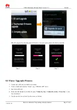
Page 15: ...start if not you need to remove the battery manually 5 3 Force Upgrade Process 1 Format micro SD card and delete its contents 2 Create a folder and named as dload copy UPDATA APP into it 3 Insert micro SD card 4 Make sure that handset is switched off press Volume Up Key Volume Down Key Power Key enter force download 5 The process bar is seen from 0 on the screen as follows ...

Page 16: ...U8800 Maintenance Manual Basic Version V1 1 Internal 2011 03 21 Huawei confidential No spreading without permission Page 16 of 61 6 After upgrade is completed handset will restart automatically ...

Page 17: ...SD card upgrade if handset shows flash screen to lead failed upgrade check whether there is a miss operation You can change a handset or a SD card to try again Error 2 If handset display below the icon on the screen check whether upgrade version is correct and change a handset or a SD card to try again Notes Make sure that battery is enough to achieve upgrade You can connect handset with charger o...

Page 18: ...ls Name Constant temperature Hot Air Gun Purpose Heat component Name Soldering Iron Purpose Repair soldering Name DC Power Supply Purpose Supply voltage and current Name Soldering Station Purpose Fix main board Name Pb free Solder Wire Purpose Join component Name Digital Multimeter Purpose Service measure Name Oscilloscope Purpose Service measure ...

Page 19: ...l Basic Version V1 1 Internal 2011 03 21 Huawei confidential No spreading without permission Page 19 of 61 Name Tool kit Purpose Assemble and Disassemble tool Name Electronic Screw Driver Purpose Assemble and Disassemble tool ...

Page 20: ...1 Huawei confidential No spreading without permission Page 20 of 61 7 Disassembly Process 4 Remove the battery 3 Remove the battery cover 2 Disassemble procedure of the U8800 is shown below 1 Make sure the ESD antistatic wrist strap connect to the ground is normal ...

Page 21: ...g without permission Page 21 of 61 7 Remove FPC of the power key from the back cover 10 Disassemble the back cover from the front cover and note the volume key 9 Disassemble another buckles of back cover 8 Disassemble the buckles of back cover 6 Remove the six screws 5 Remove the decoration cover ...

Page 22: ...ut permission Page 22 of 61 16 Remove BTB connector of the LCD 15 Remove BTB connector of the touch panel 14 Remove BTB connector of the mainboard 13 Disassemble the coaxial cable connector 12 Remove FPC of the power key from the front cover 11 Remove the back cover and note BTB connection on the board ...

Page 23: ...preading without permission Page 23 of 61 22 Disassemble the LCD module from the front cover 21 Remove the TF card FPC 20 Put up the TF card FPC 19 Heat the TF card FPC by the Hot Air Gun for 15 seconds setting temperature 150 18 Remove BTB connector of the TF card 17 Remove the mainboard ...

Page 24: ...confidential No spreading without permission Page 24 of 61 28 Put up the sub_PCB 27 Disassemble the volume key FPC 26 Remove the power key FPC 25 Put up the buckle of the power key FPC 24 Paste the protection film to the touch panel 23 Paste the protection film to the LCD ...

Page 25: ...rsion V1 1 Internal 2011 03 21 Huawei confidential No spreading without permission Page 25 of 61 32 Disassembly procedure of the U8800 is completed 31 Remove the speaker 30 Remove the receiver 29 Remove the sub_PCB from the LCD module ...

Page 26: ...03 21 Huawei confidential No spreading without permission Page 26 of 61 8 Assembly Process 4 Install the receiver 3 Install the speaker 2 Assembly procedure of the U8800 is shown below 1 Make sure the ESD antistatic wrist strap connect to the ground is normal ...

Page 27: ...o spreading without permission Page 27 of 61 10 Assemble the LCD module to the front cover 9 Rip off the protective film of the touch panel 8 Rip off the protective film of LCD 7 Install the buckle of the power key FPC 6 Install the power key FPC 5 Install the sub_PCB to the LCD module ...

Page 28: ...ential No spreading without permission Page 28 of 61 16 Assemble BTB connector of the mainboard 15 Install the coaxial cable 14 Install the mainboard and note the coaxial cable 13 Install connector of the TF card FPC 12 Install the TF card FPC 11 Install the power volume key FPC ...

Page 29: ...without permission Page 29 of 61 22 Assemble a side buckles of the back cover 21 Install the back cover and note the power key FPC 20 Install the volume key to the front cover 19 Fix the power key FPC to the front cover 18 Install BTB connector of the touch panel 17 Install BTB connector of the LCD ...

Page 30: ...uawei confidential No spreading without permission Page 30 of 61 28 Install the four screws 27 Install the decoration cover 26 Install the two screws 25 Paste the TF card sheet 24 Fix the power key FPC to the back cover 23 Assemble the other buckles of the back cover ...

Page 31: ...nce Manual Basic Version V1 1 Internal 2011 03 21 Huawei confidential No spreading without permission Page 31 of 61 31 Assembly procedure of the U8800 is completed 30 Install the battery cover 29 Install the battery ...

Page 32: ...l is in good condition and restored to default settings 9 1 Principle Instruction The U8800 develops basing on MSM7230 IC of Qualcomm Phone mostly consists of base band module RF module and PM module The MSM7230 IC of base band is divided into RF signal disposal and intelligent interface connection The QTR 8600 IC of RF module achieves among terminal and base station communications The PM8085 IC o...

Page 33: ... supply by DC power Short circuit of VBAT signal or VPH_PWR signal causes high current usually Reference Figure 9 1 High current Check J1501 J1102 whether it is damaged Check U1001 whether it is short circuit Check U3302 U3402 U3501Whethe r it is short circuit N Replace the U1001 Y Check U301 whether it is short circuit N N Replace the U201 N Replace faulty components Y Replace the U301 Y Replace ...

Page 34: ...A 500mA scope as power supply by DC power The problem of software or FLASH causes the failure usually Reference Figure 9 2 J1501 Pin3 VBAT 3 7 4 2V J1102 Pin1 test LB1101 5 0V Figure9 1 U3302 VBAT test C3302 3 7 4 2V U3501 VBAT test C3501 3 7 4 2V U1001 VPH_PWR test L1001 3 7V U201 U3302 U3501 U3402 U1001 CHG_CHIP J1102 U3402 VCC test C3406 3 7 4 2V U301 U301 VPH_PWR test C409 3 7V Q301 MOSFET ...

Page 35: ...tial No spreading without permission Page 35 of 61 U301 VREG_MSMA test C402 2 85V Figure9 2 U301 U301 VREG_MSMP test C430 1 3V U301 VREG_MSME test C433 2 6V U301 VREG_S2 RFRX test L403 1 3V U301 VREG_S4 RFTX test L405 2 2V X401 Pin1 19 2MHz U301 VREG_WLAN test C434 3 0V U1701 X401 ...

Page 36: ...U8800 Maintenance Manual Basic Version V1 1 Internal 2011 03 21 Huawei confidential No spreading without permission Page 36 of 61 9 3 Charge Failure Reference Figure 9 1 ...

Page 37: ...Manual Basic Version V1 1 Internal 2011 03 21 Huawei confidential No spreading without permission Page 37 of 61 9 4 light Sensor Failure Reference Figure 9 3 Figure9 3 D601 D603 Infrared Emitting Diode U601 VREG_L10 2 7V ...

Page 38: ...Manual Basic Version V1 1 Internal 2011 03 21 Huawei confidential No spreading without permission Page 38 of 61 9 5 SIM Card Failure Reference Figure 9 4 J1601 Measure resistance value Figure9 4 D1601 ESD Protected U201 ...

Page 39: ... No spreading without permission Page 39 of 61 9 6 TF Card Failure TF card failure Check whether FPC of the TF_card is normal Y Replace the FPC N Measure whether the supply voltage of the TF_card is normal Y Replace the U301 N Replace the U201 9 7 Display Failure Reference Figure 9 5 ...

Page 40: ...enance Manual Basic Version V1 1 Internal 2011 03 21 Huawei confidential No spreading without permission Page 40 of 61 Figure9 5 J1201 LCD BTB connector U1201 D1201 LCD module match circuit J1401 TP BTB connector ...

Page 41: ...ce Manual Basic Version V1 1 Internal 2011 03 21 Huawei confidential No spreading without permission Page 41 of 61 9 8 Touch Panel Failure Reference Figure 9 5 9 9 Audio Failure 9 9 1 No Ring Tone Reference Figure 9 6 ...

Page 42: ... Page 42 of 61 No ring tone Measure whether resistance value of the speaker is 8Ω Y Y Replace the speaker N Measure whether the U301 on the sub PCB is normal Replace the U301 on the sub_PCB N Replace the U201 Replace U3701 check whether it is normal N End Y Check whether the sub PCB is normal Replace the sub_PCB N Y ...

Page 43: ...l Basic Version V1 1 Internal 2011 03 21 Huawei confidential No spreading without permission Page 43 of 61 Figure9 6 U201 U301 VPH_PWE test LB301 3 7V SP301 SPK_OUT_P SP301 SPK_OUT_N MIC2 MIC 1 2KΩ U301 Audio PA U3701 RF Chip ...

Page 44: ...800 Maintenance Manual Basic Version V1 1 Internal 2011 03 21 Huawei confidential No spreading without permission Page 44 of 61 9 9 2 Voice Transmitting Failure Reference Figure 9 6 9 9 3 Receiver Failure ...

Page 45: ...ailure Reference Figure 9 7 Earphone failure Check whether J801 is normal Y Replace the J801 N Measure whether voltage of the U3701 U801 is normal Y Replace the U201 N Replace faulty components Measure whether the D801 is normal N Replace the D801 Y Measure whether the Z801 is normal N Replace the Z801 Replace the sub_PCB whether it is normal Y End Y N ...

Page 46: ...ernal 2011 03 21 Huawei confidential No spreading without permission Page 46 of 61 9 11 Camera Failure Reference Figure 9 7 Figure9 7 J801 U801 VPH_PWE test C814 3 7V Z801 AudioVaristor D801 ESD Protected U801 TVOUT Analog Switch Camera Camera modue ...

Page 47: ...rnal 2011 03 21 Huawei confidential No spreading without permission Page 47 of 61 9 12 Vibration Failure Figure9 8 U4201 VREG_S3 Test C4225 1 8V U4201 X4201 J4201 WIFI Connector U4201 VREG_WLAN Test C4222 3 0V U201 U3701 X4201 Test pin1 signal 40MHz ...

Page 48: ...ailure Reference Figure 9 8 WIFI BT failure Check whether the WIFI coaxial cable is normal Y Replace the coaxial cable N Measure whether the J4201 is normal Y Replace the J4201 N Measure whther output signal of the X4201 is 26MHz Y Measure whether the U4201 U3701 is normal Y Replace the U201 Replace the X4201 N Replace the U4201 WIFI U3701 BT N ...

Page 49: ...ure 9 9 GPS failure Check whether the GPS antenna is normal Y Replace the antenna N Replace Z4101 Z4102 check whether it is normal N Replace U4101 check whether it is normal End Y N End Y Measure U3701 whether it is normal Y Replace the U201 Replace the U3701 N Figure9 9 U4101 Z4101 GPS module match circuit U1401 Semiconductor Sensor U1401 VDD test C1404 2 7V ...

Page 50: ...i confidential No spreading without permission Page 50 of 61 9 15 Accelerometer Electronic Compass Failure Reference Figure 9 9 A C failure N Check J1401 whether it is normal Y Replace the J1401 N Measure U1401 whether it is normal Y Replace the U201 Replace the U1401 N ...

Page 51: ...rameter whether is correct the wrong RF parameter can cause the failure usually Reference Figure 9 10 Signal Failure W900MHz Measure VREG_RF whether voltage is normal Measure whether two pins of the U3201 are connection Replace the U3201 Replace U3202 check whether it is normal BT CT Replace U201 Y N Y Y Y N Replace U3404 check whether is normal Y Measure whether the U3701 is normal Replace the U3...

Page 52: ...ermission Page 52 of 61 Figure9 10 U301 U201 U3701 U3701 VREG_S4 test C4003 2 2V U3201 Check U3201 U3202 RF Switch check output U3404 Duplex filter W900 U3701 VREG_S2 RFRX test C3926 1 3V U3304 Duplex filter W2100 U3603 Unbuffer Single Inverter G1900 U3602 RF Switch GSM1900 1800 U3602 RF Switch GSM1900 1800 ...

Page 53: ...er is correct the wrong RF parameter can cause the failure usually Reference Figure 9 10 Signal Failure W2100MHz Measure VREG_RF whether voltage is normal Measure whether two pins of the U3201 are connection Replace the U3201 Replace U3202 check whether it is normal BT CT Replace U201 Y N Y Y Y N Replace U3304 check whether is normal Y Measure whether the U3701 is normal Replace the U3701 N N N Re...

Page 54: ... Reference Figure 9 10 Signal Failure GSM850 900 Measure VREG_RF whether voltage is normal Measure whether two pins of the U3201 are connection Replace the U3201 Replace U3202 check whether it is normal BT CT Replace U201 Y N Y Y Y N Measure whether the U3701 is normal Replace the U3701 N Replace the U301 N 9 16 4RF Receiving Failure GSM1800 1900 Reference Figure 9 10 ...

Page 55: ...M1800 1900 Measure VREG_RF whether voltage is normal Measure whether two pins of the U3201 are connection Replace the U3201 Replace U3202 check whether it is normal BT CT Replace U201 Y N Y Y Y N Measure whether the U3701 is normal Replace the U3701 N Replace the U301 N Check U3601 U3602 U3603 whether they are normal Replace faulty components N Y ...

Page 56: ...MA900MHz Reference Figure 9 10 Figure 9 11 Signal Failure W900MHz Measure VREG_RF whether voltage is normal Replace U3202 check whether it is normal CT MT Replace U3404 check whether it is normal Replace U201 Y N Y Y Y N Replace Z3401 check whether is normal Y Measure whether the U3701 is normal Replace the U3701 N N N Replace the U301 Measure U3402 whether it is normal N Y Replace the U3402 ...

Page 57: ...nal 2011 03 21 Huawei confidential No spreading without permission Page 57 of 61 Figure9 11 U3401 VBAT test C3406 3 7 4 2V U301 U3302 U3501 U3301 TX filter W2100 U3402 U3501 VBAT test C3501 3 7 4 2V U3302 VBAT test C3302 3 7 4 2V Z3401 TX filter W900 ...

Page 58: ...ence Figure 9 10 Figure 9 11 Signal Failure W2100MHz Measure VREG_RF whether voltage is normal Replace U3202 check whether it is normal CT MT Replace U3304 check whether it is normal Replace U201 Y N Y Y Y N Replace U3301 check whether is normal Y Measure whether the U3701 is normal Replace the U3701 N N N Replace the U301 Measure U3302 whether it is normal N Y Replace the U3402 ...

Page 59: ... 9 17 3 RF Transmitting Failure GSM Reference Figure 9 10 Figure 9 11 Signal Failure GSM Measure VREG_RF whether voltage is normal Replace U3202 check whether it is normal CT MT Replace U201 Y N Y Y N Measure whether the U3701 is normal Replace the U3701 N Replace the U301 Measure U3501 whether it is normal N Replace the U3501 Y ...

Page 60: ...Volume key to continue 5 Compass test 1 Compass test Check the delicacy of a compass 6 Approach test 1 approach current value Let your hands chose to the sensor then the screen value will change press Volume key to continue 7 Environment light test 1 Environment light test Let your hands chose to the sensor then the screen value will change press Volume key to continue 1 White screen the screen wi...

Page 61: ...s color will turned after press down successfully press Volume key to continue 15 Blue tooth test 1 Blue tooth test A ready Bluetooth machine needed to make this step test press Volume key to continue The screen will display testing results the screen prompt whether need to reset factory settings Press End key quit test 10 2 Voice Call Test 1 Insert SIM card to mobile phone press and hold Power ke...

Reviews: