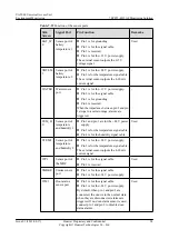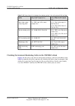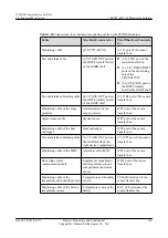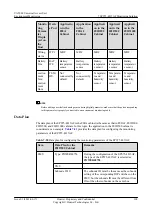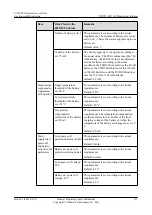
Cable
One End Connects to...
The Other End Connects to...
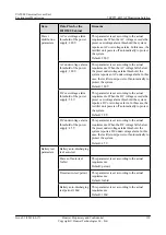
Test and alarm cable (3): STACK OUT port on the
HWCF transfer board of the
HABD shelf
l
(3.2): JTD1 port of the sensor
transfer box
l
(3.3-3.4): RS485/RS232 ports
on the monitoring unit of the
EPS75-4815AF
l
(3.1): STACK IN port on the
HWTF transfer board of the
HABF shelf
Test and alarm
subtending cable
(4): STACK OUT port on the
HWTF transfer board of the
HABF shelf
(4): JTD2 port of the sensor transfer
box
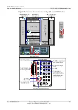
Checking Environment Monitoring Cables in the AC-powered F02A Cabinet
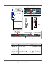
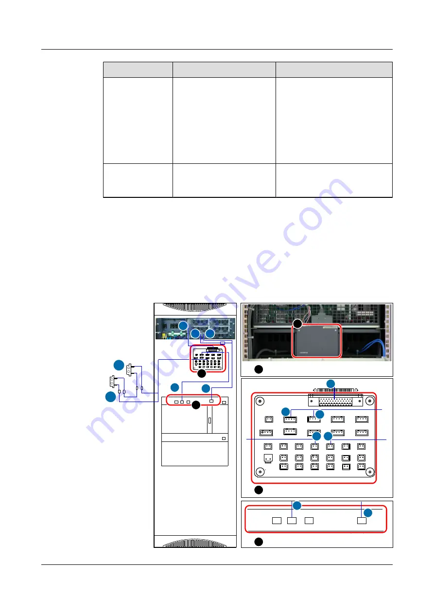
shows the connections of environment monitoring cables in the AC-powered F02A
cabinet.
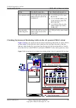
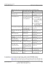
describes the cable connections. By referring to the cable connection
diagram, check whether the connections from the sensors to the sensor transfer box, from the
sensor transfer box to the EPMU02T, and from the EPMU02T to the control system are correct.
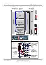
Figure 7-10
Connections of environment monitoring cables in the AC-powered F02A cabinet
JD3
JD0
JD1
JD2
N-ESC
TEST
PWR-ALM FAN-ALM
View of fan backplane
C
3
2
Rear view of transfer box
B
A
Partial enlarged drawing of ports
W1
JTM1
JTD1
JTD2
J1
W1
1.1
1
4
B
HWTB
HW
JP2
JP1
JD2
JD1
JD0
PWR-ALM
TEST
HABA
FAN-ALM
JD3
N-ESC
W1
JTM
1
JTD
1
JTD
2
J
1
2
A
C
4
3
1.2
1.1
3.1
3.2
5
To
MDF
2.1
2.2
UA5000 Universal Access Unit
Environment Monitoring
7 EPS75-4815AF Monitoring Solution
Issue 01 (2012-08-17)
Huawei Proprietary and Confidential
Copyright © Huawei Technologies Co., Ltd.
98

