background image

UPS2000-A-(6 kVA-10 kVA) 
User Manual 

3 Installation 


Issue 05 (2019-12-19) 

Copyright © Huawei Technologies Co., Ltd. 

51 


Table 3-4


Rated voltages and currents for backfeed protection contactors 

Model 

Rated Voltage and Current 

Recommended 
Contactor Model 

UPS2000-A-6KTTS-S  220, 230, or 240 V AC, 40 A 

LC1-D40A (Schneider 
contactor) 

UPS2000-A-6KTTL-

UPS2000-A-6KTTS-P  208, 220, 230, or 240 V AC, 40 A 


Single-phase: 
LC1-D40A (Schneider 
contactor) 


Dual-live-wire: 
AF50-30-11*70 (ABB) 

UPS2000-A-6KTTL-

UPS2000-A-10KTTS-

220, 230, or 240 V AC, 65 A 

LC1-D50A (Schneider 
contactor) 

UPS2000-A-10KTTL-

UPS2000-A-10KTTS-

208, 220, 230, or 240 V AC, 65 A 


Single-phase: 
LC1-D50A (Schneider 
contactor) 


Dual-live-wire: 
AF50-30-11*70 (ABB) 

UPS2000-A-10KTTL-


Table 3-5


Control relay parameters 

Recommended Model 

Parameters 

HF18FF/012 (HONGFA control relay) 

Dry contact: NC 

Breaking capability: 250 V AC, 5 A 

Coil: 12 V rated voltage; rated current of 
less than 1 A 

MY2N-J DC12V (OMRON control relay) 

HJ2-L-DC12V (Panasonic control relay) 


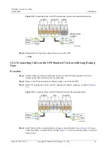
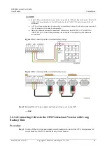
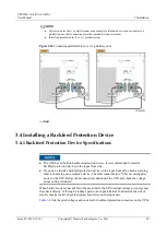
3.4.2 Feedback Prevention Connections (With Dry Contract 
Control) 

Figure 3-25

 and 

Figure 3-26

 show backfeed protection connections (with dry contract 

control). 

Summary of Contents for UPS2000-A Series

Page 1: ...UPS2000 A 6 kVA 10 kVA User Manual Issue 05 Date 2019 12 19 HUAWEI TECHNOLOGIES CO LTD ...

Page 2: ...tomer All or part of the products services and features described in this document may not be within the purchase scope or the usage scope Unless otherwise specified in the contract all statements information and recommendations in this document are provided AS IS without warranties guarantees or representations of any kind either express or implied The information in this document is subject to c...

Page 3: ...ineer Data Configuration Engineer Maintenance Engineer Symbol Conventions The symbols that may be found in this document are defined as follows Symbol Description Indicates a hazard with a high level of risk which if not avoided will result in death or serious injury Indicates a hazard with a medium level of risk which if not avoided could result in death or serious injury Indicates a hazard with ...

Page 4: ...ironment deterioration Change History Changes between document issues are cumulative The latest document issue contains all the changes made in earlier issues Issue 05 2019 12 19 Added the USB port description for the new product structure Issue 04 2019 05 05 Updated the section Operating Environment Issue 03 2018 01 16 Added the description of device application scenarios Issue 02 2017 11 27 Upda...

Page 5: ...6 2 2 2 Working Modes 17 2 3 Appearance 17 2 4 Optional Components 23 3 Installation 27 3 1 Preparations 27 3 1 1 Site 27 3 1 2 Tools 29 3 1 3 Power Cables 30 3 1 4 Unpacking and Checking 33 3 2 Single UPS Installation 34 3 2 1 Routing Cables 34 3 2 2 Securing a UPS 35 3 2 3 Connecting Cables 39 3 2 3 1 Connecting Cables to the UPS Standard Version with Standard Backup Time 39 3 2 3 2 Connecting C...

Page 6: ...ens 57 4 5 1 Starting the UPS in Normal Mode 61 4 5 2 Starting the UPS in Battery Mode 61 4 6 LCD Menu Hierarchy 62 4 6 1 Control Menu 65 4 6 2 Setting Menu 67 4 6 3 Active Alarm Display Menu 78 4 6 4 Historical Alarms Display Menu 79 5 Operations 81 5 1 Checking Before Powering On the UPS 81 5 2 Single UPS Operations 81 5 2 1 Starting the UPS 81 5 2 2 Shutting down the UPS 88 5 2 3 Performing EPO...

Page 7: ...erly Maintenance 116 7 2 4 Yearly Maintenance 116 8 Troubleshooting 118 9 Technical Specifications 120 9 1 Physical Specifications 120 9 2 Environmental Specifications 121 9 3 Mains Input Electrical Specifications 121 9 4 Bypass Input Electrical Specifications 122 9 5 Output Electrical Specifications 123 9 6 Battery Electrical Specifications 124 9 7 ECO Feature 129 9 8 Parallel Feature 130 9 9 Saf...

Page 8: ...taining the equipment The safety instructions in this document are only supplements to local laws and regulations Huawei will not be liable for any consequences of the following circumstances Operation beyond the conditions specified in this document Installation or use in environments which are not specified in relevant international or national standards Unauthorized modifications to the product...

Page 9: ...ace or terminal measure the contact point voltage and ensure that there is no risk of electric shock After installing the equipment remove idle packing materials such as cartons foam plastics and cable ties from the equipment area In the case of a fire immediately leave the building or the equipment area and turn on the fire alarm bell or make an emergency call Do not enter the building on fire in...

Page 10: ...cannot be exposed to an outdoor environment for a long period of time Before operations ensure that the equipment is firmly secured to the floor or other solid objects such as a wall or an installation rack Do not use water to clean electrical components inside or outside of a cabinet Do not change the structure or installation sequence of equipment without permission Do not touch a running fan wi...

Page 11: ...he sources and degree of various potential hazards in equipment installation operation maintenance Trained personnel personnel who are technically trained have required experience are aware of possible hazards on themselves in certain operations and are able to take protective measures to minimize the hazards on themselves and other people Operators operation personnel who may come in contact with...

Page 12: ...hat a distance of at least 30 mm exists between the cables and heat generating components or areas This prevents damage to the insulation layer of the cables Do not route cables behind the air intake and exhaust vents of the equipment Ensure that cables meet the VW 1 flame spread rating requirements Bind cables of the same type together When routing cables of different types ensure that they are a...

Page 13: ...ents To prevent fire due to high temperature ensure that the ventilation vents or heat dissipation system are not blocked when the equipment is running Install the equipment in an area far away from liquids Do not install it under areas prone to condensation such as under water pipes and air exhaust vents or areas prone to water leakage such as air conditioner vents ventilation vents or feeder win...

Page 14: ...nt personnel Carry the operation machinery and tools properly to prevent them from falling off and causing injuries Personnel involving working at heights are not allowed to throw objects from the height to the ground or vice versa Objects should be transported by tough slings hanging baskets highline trolleys or cranes Ensure that guard rails and warning signs are set at the edges and openings of...

Page 15: ...d confirm its load bearing capacity Do not overload it Ensure that the ladder is securely positioned The recommended angle for a ladder against the floor is 75 degrees as shown in the following figure An angle rule can be used to measure the angle Ensure that the wider end of the ladder is at the bottom or protective measures have been taken at the bottom to prevent the ladder from sliding When cl...

Page 16: ...heavy objects When moving the equipment by hand wear protective gloves to prevent injuries Move or lift the equipment by holding its handles or lower edges Do not hold the handles of modules such as power supply units fans and boards that are installed in the equipment because they cannot support the weight of the equipment Avoid scratching the cabinet surface or damaging cabinet components and ca...

Page 17: ...stored for more than 90 days charge them in time Otherwise the battery lifespan may be affected Install the UPS in an area far away from liquids Do not install it under areas prone to water leakage such as air conditioner vents ventilation vents or feeder windows of the equipment room Ensure that no liquid enters the UPS to prevent short circuits Ensure that there is no condensation inside the equ...

Page 18: ... Basic Requirements Before operating batteries carefully read the safety precautions for battery handling and master the correct battery connection methods Do not expose batteries at high temperatures or around heat generating devices such as sunlight fire sources transformers and heaters Excessive heat exposure may cause the batteries to explode Do not burn batteries Otherwise the batteries may e...

Page 19: ...e and secure batteries horizontally Note the polarities when installing batteries Do not short circuit the positive and negative poles of the same battery or battery string Otherwise the battery may be short circuited Check battery connections periodically ensuring that all bolts are securely tightened When installing batteries do not place installation tools on the batteries Battery Short Circuit...

Page 20: ...precautions described in this section There is a risk of explosion if a battery is replaced with an incorrect model A battery can be replaced only with a battery of the same or similar model recommended by the manufacturer When handling a lithium battery do not place it upside down tilt it or bump it with other objects Keep the lithium battery loop disconnected during installation and maintenance ...

Page 21: ...10 kVA User Manual 1 Safety Information Issue 05 2019 12 19 Copyright Huawei Technologies Co Ltd 14 Exercise caution when setting battery parameters Incorrect settings will affect the power supply and battery lifespan ...

Page 22: ...s of the four models need to be described UPS2000 A 6KTTL S 6 kVA standard version with long backup time UPS2000 A 6KTTS P 6 kVA professional version with standard backup time UPS2000 A 6KTTL P 6 kVA professional version with long backup time UPS2000 A 10KTTS S 10 kVA standard version with standard backup time The 10 kVA model is used as a collective name when the common features or parameters of ...

Page 23: ... Product category UPS short for uninterruptible power system 2 Product series 2000 3 UPS subcategory A series 4 Output capacity Unit VA 6K 6 kVA 10K 10 kVA 5 UPS type TT tower mounted UPS 6 Standard Long backup time model S standard backup time model using built in batteries that provide standard backup time L long backup time model using external large capacity batteries that provide long backup ...

Page 24: ...step up transformer boosts the DC power supplied from batteries Then the inverter converts the DC power into stable AC power for powering loads Bypass mode The mains supplies power directly to loads after filtering The UPS transfers to bypass mode when overload overtemperature or faults occur This mode does not provide battery backup capability ECO mode If the bypass voltage and frequency are in t...

Page 25: ... 2 3 Side view 1 Control panel 2 Castor 3 Mounting bracket optional 4 Brake pad Mounting brackets are optional for UPSs with standard backup time and battery boxes and are not required for UPSs with long backup time Figure 2 4 shows the rear view of the 6 kVA 10 kVA UPS standard version with standard backup time ...

Page 26: ...standard backup time 1 AC input circuit breaker 2 Optional card slot under the cover 3 USB porta security protection mechanism supported 4 Maintenance bypass status MBS port 5 Emergency power off EPO port 6 AC input terminal under the cover 7 AC output terminal under the cover Figure 2 5 shows the rear view of the 6 kVA 10 kVA UPS standard version with long backup time ...

Page 27: ...AC input circuit breaker 2 Optional card slot under the cover 3 USB porta security protection mechanism supported 4 Maintenance bypass status MBS port 5 Emergency power off EPO port 6 AC input terminal under the cover 7 AC output terminal under the cover 8 Battery wiring terminal under the cover Figure 2 6 shows the rear view of the 6 kVA 10 kVA UPS professional version with long backup time ...

Page 28: ...Optional card slot under the cover 3 EPO port 4 USB porta security protection mechanism supported 5 MBS port 6 Parallel port 7 Maintenance bypass circuit breaker 8 AC output circuit breaker 9 AC input terminal block under the cover 10 Jumper terminal for a single UPS under the cover 11 AC output terminal under the cover Figure 2 7 shows the rear view of the UPS2000 A 6 kVA 10 kVA professional vers...

Page 29: ...a security protection mechanism supported 5 MBS port 6 Parallel port 7 Maintenance bypass circuit breaker 8 AC output circuit breaker 9 AC input terminal block under the cover 10 Jumper terminal for a single UPS under the cover 11 AC output terminal under the cover 12 Battery wiring terminal under the cover a The USB port supports the standard Modbus protocol and connects to a PC through a USB cab...

Page 30: ...re OT terminals connected to the UPS Ambient temperature and humidity sensor ENR1DETA Sensor The ambient temperature ranges from 0 50º C The ambient humidity ranges from to 0 100 RH It is used together with a Simple Network Management Protocol SNMP card The cable is delivered with the SNMP card by default and is 1 5 m long SNMP card RMS SNMP01A Monitors the UPS and provides the Ethernet networking...

Page 31: ...00 A 10 kVA Standard battery box 7 Ah 20 batteries ESS 240V12 2 7AhBPV BA Consists of two strings of twenty 12 V 7 Ah lead acid batteries connected in series It is a standard configuration for the 6 kVA UPS A maximum of two battery boxes can be connected in parallel A UPS with standard backup time does not support external battery boxes A UPS with long backup time can be configured with one or two...

Page 32: ...xes and UPSs with standard backup time The number of supports required is the same as the number of battery boxes and UPSs with standard backup time N A GSM modem Select a GSM modem provided by Huawei based on site requirements Provide the GSM modem functions by working with the SNMP card The GSM modem is used with the SNMP card The number of GSM modems is the same as the number of SNMP cards Ante...

Page 33: ...kVA 10 kVA User Manual 2 Overview Issue 05 2019 12 19 Copyright Huawei Technologies Co Ltd 26 Component Model Function Remarks The input port of the power adapter of the modem complies with international standards ...

Page 34: ...Environment Do not install the UPS in an environment outside the specifications Keep the UPS far away from water heat sources and flammable and explosive substances Install the UPS in an environment free of dust volatile gas salt and corrosive materials Avoid direct sunlight Do not install the UPS in environments with conductive metal scraps in the air The ideal operating temperature for batteries...

Page 35: ...PS2000 A 6 kVA 10 kVA installation dimensions Unit mm Clearances The distance between UPS air vents and the wall or obstacle is greater than or equal to 500 mm Reserve a clearance of at least 500 mm respectively from the front and rear panels of the UPS to the wall or adjacent equipment to facilitate ventilation and heat dissipation as shown in Figure 3 2 ...

Page 36: ...d clearances Unit mm 3 1 2 Tools Get installation tools insulated to prevent electric shocks Table 3 1 lists the installation tools Table 3 1 Tools Tools Clamp meter Multimeter Label Phillips screwdriver PH 2 mm x 150 mm or PH 3 mm x 250 mm Flat head screwdriver 2 mm x 80 mm Torque screwdriver COAX crimping tool Diagonal pliers ...

Page 37: ...logies Co Ltd 30 Tools Wire stripper Polyvinyl chloride PVC insulation tape Cotton cloth Brush Heat shrink tubing Heat gun Electrician s knife Protective gloves ESD gloves Insulated gloves Hydraulic pliers Cable tie Hammer drill and drill bit φ16 Rubber mallet N A N A N A N A 3 1 3 Power Cables ...

Page 38: ...ers for both the N wire and L wire No independent circuit breaker is allowed for only the N wire For the 6 kVA model use ground cables that have a cross sectional area of 6 mm2 and M4 OT terminals that have a cross sectional area of 6 mm2 For the 10 kVA model use ground cables that have a cross sectional area of 10 mm2 and M6 OT terminals that have a cross sectional area of 10 mm2 Table 3 2 lists ...

Page 39: ... cable specifications for the UPS professional version Model Wiring Termin al Rated Voltage External Circuit Breaker ELCB Cross se ctional Area Termi nal Type Torqu e for Tighte ning Bolts 6 kVA professional version with standard backup time Input 208 V AC 220 V AC 230 V AC or 240 V AC 50 A feature D 100 mA 6 mm2 OT 6 mm2 M4 termin al 1 4 N m Output 50 A feature D N A 6 kVA professional version wi...

Page 40: ...e Input 208 V AC 220 V AC 230 V AC or 240 V AC 63 A feature D 100 mA 10 mm2 OT 10 mm2 M6 termin al 2 8 N m Output 63 A feature D N A Battery 240 V DC 63 A N A 10 mm2 If customers purchase input and output power cables by themselves use the cables that comply with standards proposed by Underwriters Laboratories UL or International Electrotechnical Commission IEC 3 1 4 Unpacking and Checking Figure ...

Page 41: ...Move the UPS to the installation position Step 3 Unpack the case Step 4 Check the UPS 1 Visually inspect the UPS appearance for shipping damage If any shipping damage is found report it to the carrier immediately 2 Check the UPS bar code which is at the top of the UPS and ensure that it complies with the order If there is any discrepancy contact your local Huawei office immediately 3 Check that th...

Page 42: ... 4 Routing cables 1 Cable between battery boxes 2 Cable between the UPS and the battery box 3 AC input power cable 4 AC output power cable 3 2 2 Securing a UPS Securing the UPS Using Brake Pads Step 1 Move the UPS to the installation position Step 2 Press down the brake pads to immobilize the UPS as shown in Figure 3 5 ...

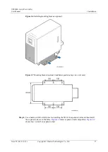
Page 43: ...ecuring a UPS Step 3 If mounting brackets are required secure them to the UPS using M6x12 bolts as shown in Figure 3 6 Figure 3 7 shows the installation positions of the mounting brackets Mounting brackets are optional for UPSs with standard backup time and battery boxes and are not required for UPSs with long backup time ...

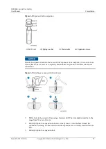
Page 44: ... mounting brackets optional Figure 3 7 Mounting bracket optional installation positions top view unit mm Step 4 Use a hammer drill to drill holes for installing the M12x60 expansion bolts and then install the expansion sleeve in the holes Figure 3 8 shows expansion bolt composition Figure 3 9 shows how to install an expansion bolt ...

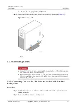
Page 45: ...he hole The expansion sleeve must be completely buried under the ground to facilitate subsequent installation Figure 3 9 Installing an expansion bolt unit mm 1 Drill a hole in the concrete floor using a hammer drill The hole depth should be in the range from 52 mm to 60 mm 2 Partially tighten the expansion bolt and vertically insert it into the hole Knock the expansion bolt using a rubber mallet u...

Page 46: ...L N correctly For a UPS with long backup time connect the battery terminals correctly Before connecting cables ensure that the input and output circuit breakers are OFF For a UPS with long backup time ensure that the battery circuit breakers are OFF Perform all tasks with the power off 3 2 3 1 Connecting Cables to the UPS Standard Version with Standard Backup Time Procedure Step 1 Switch off the A...

Page 47: ... wiring cover End 3 2 3 2 Connecting Cables to the UPS Professional Version with Standard Backup Time Procedure Step 1 Switch off the AC input and output circuit breakers at the rear of the UPS and the upstream AC circuit breaker of the UPS Step 2 Remove the AC input and output wiring cover from the UPS Step 3 Install a short circuit bar for a single UPS Step 4 Install AC output power cables and t...

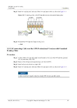
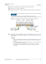
Page 48: ...nput circuit breaker at the rear of the UPS the upstream AC circuit breaker of the UPS and the battery circuit breaker Step 2 Remove the AC input output and battery wiring cover from the UPS Step 3 Install AC output power cables and AC input power cables in sequence as shown in Figure 3 13 Figure 3 13 Connecting cables to the UPS standard version with long backup time Step 4 Install battery cables...

Page 49: ...efault configurable One or two battery boxes can be connected For details see the ESS 240V12 2 9AhBPVBA 7AhBPVBA Quick Guide If longer backup time is required the large battery rack solution is recommended Figure 3 14 Connecting cables to external battery strings Figure 3 15 Connecting cables to external battery boxes Step 5 Reinstall the AC input output and battery wiring cover on the UPS End 3 2...

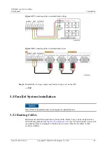
Page 50: ...ables to external battery strings or external battery boxes Figure 3 17 shows connecting cables to external battery strings Figure 3 18 shows connecting cables to external battery boxes Install a DC circuit breaker between a battery string and the UPS with long backup time Install a 50 A 300 V DC circuit breaker for the 6 kVA model and a 63 A 300 V DC circuit breaker for the 10 kVA model A UPS wit...

Page 51: ...output and battery wiring cover on the UPS End 3 3 Parallel System Installation Only UPSs of the professional version support the parallel feature 3 3 1 Routing Cables Determine the installation positions and route cables Battery boxes can be configured for a UPS with long backup time Figure 3 19 and Figure 3 20 use a UPS professional version with long backup time as an example to illustrate how t...

Page 52: ...ry cables 1 Cable between battery boxes 2 Cable between the battery box and the UPS Figure 3 20 Routing input and output cables 1 AC input power cable 2 AC output power cable 3 3 2 Securing UPSs in a Parallel System Procedure Step 1 Secure each UPS in a parallel system by following the instructions provided in 3 2 2 Securing a UPS End ...

Page 53: ...ckup Time Procedure Step 1 Switch off the AC input and output circuit breakers at the rear of each UPS in the parallel system and the upstream AC circuit breaker of each UPS Step 2 Remove the AC input and output wiring cover from each UPS in the parallel system Step 3 Install AC output power cables and then AC input power cables for each UPS in the parallel system as shown in Figure 3 21 ...

Page 54: ...strate how to connect cables to a parallel system Cable connections for other parallel systems are similar Figure 3 21 Connecting cables to the UPS professional version with standard backup time 1 AC input circuit breaker of UPS 1 2 AC input circuit breaker of UPS 2 3 AC output circuit breaker of UPS 1 4 AC output circuit breaker of UPS 2 5 General AC input circuit breaker of the parallel system 6...

Page 55: ...g Figure 3 22 Connecting parallel cables to a 1 1 parallel system End 3 3 4 Connecting Cables to Parallel UPSs Professional Version with Long Backup Time Procedure Step 1 Switch off the AC input circuit breaker at the rear of each UPS in the parallel system the upstream AC circuit breaker of each UPS and the battery circuit breaker of each UPS Step 2 Remove the AC input AC output and battery wirin...

Page 56: ...systems are similar Figure 3 23 Connecting cables to the UPS professional version with long backup time 1 AC input circuit breaker of UPS 1 2 AC input circuit breaker of UPS 2 3 AC output circuit breaker of UPS 1 4 AC output circuit breaker of UPS 2 5 General AC input circuit breaker of the parallel system 6 General AC output circuit breaker of the parallel system Step 4 Install battery cables to ...

Page 57: ...otection device It is recommended to install a backfeed protection device on the input front side If you do no install a backfeed protection device on the input front side attach a warning label to the main power isolation device The label reads like this This circuit supplies power to the UPS Before cable connection disconnect the UPS and check the voltage across wiring terminals When battery mod...

Page 58: ... 6KTTL P UPS2000 A 10KTTS S 220 230 or 240 V AC 65 A LC1 D50A Schneider contactor UPS2000 A 10KTTL S UPS2000 A 10KTTS P 208 220 230 or 240 V AC 65 A Single phase LC1 D50A Schneider contactor Dual live wire AF50 30 11 70 ABB UPS2000 A 10KTTL P Table 3 5 Control relay parameters Recommended Model Parameters HF18FF 012 HONGFA control relay Dry contact NC Breaking capability 250 V AC 5 A Coil 12 V rat...

Page 59: ...A 10 kVA User Manual 3 Installation Issue 05 2019 12 19 Copyright Huawei Technologies Co Ltd 52 Figure 3 25 Bypass backfeed protection connections for the UPS2000 A 6 kVA 10 kVA single phase input single phase output ...

Page 60: ...ets engineering requirements 2 Cable connections Power cables and battery cables are tightened to specified torques using a torque wrench connected correctly and free of damage 3 Cable connections for USB ports and network ports Cables to USB ports and network ports are connected correctly and securely 4 Cable labels Labels are neatly attached to both ends of each cable and the information on the ...

Page 61: ...awei Technologies Co Ltd 54 No Item Expected Result cable and the equipment room ground bar which must be less than 0 1 ohm 6 Distances between cable ties Distances between cable ties are the same and no burr exists 7 Operating environment Clean the conductive air and other sundries ...

Page 62: ...UPS controls UPS running displays running data and allows you to set parameters and view alarms Figure 4 1 shows the control panel Figure 4 1 Control panel 1 Mains indicator 2 Battery indicator 3 Bypass indicator 4 Fault indicator 5 Enter Startup Battery Self Check Mute button 6 Down button 7 Up button 8 Shutdown Back button 4 2 Indicators Table 4 1 describes the indicators on the control panel ...

Page 63: ...is in ECO mode when the mains indicator and bypass indicator are both on 4 3 Functional Buttons The control panel provides four buttons to start and shut down the UPS and set parameters Table 4 2 describes the buttons Table 4 2 Button description Button Meaning Description ESC Shutdown Back On the default screen press ESC for more than 5 seconds Release the button when you hear a beep sound The in...

Page 64: ...f check After the UPS starts in normal mode it transfers to battery mode for 10 seconds to check that the battery status if no battery is connected 16 1 no battery alarm is displayed and that the UPS can transfer to battery mode The purpose is to prevent power backup failure when the UPS needs to transfer to battery mode If you do not press any button within 60 seconds the default screen is displa...

Page 65: ...of the startup screen Table 4 4 describes the menu icons and Table 4 5 describes the working mode icons Table 4 4 Icons on the screen No Meaning Remarks 1 Battery information Battery capacity Battery discharge status 76 100 Indicators 1 2 and 3 are steady on and indicator 4 blinks 51 75 Indicators 1 and 2 are steady on and indicator 3 blinks 26 50 Indicator 1 is steady on and indicator 2 blinks 0 ...

Page 66: ... fault ID Backup time or alarm ID 6 Alarm status The indicator is steady on when a critical alarm is generated blinks when a minor alarm is generated and is off when no alarm is generated 7 Mute indicator If the indicator is on the buzzer is muted If the indicator is off the buzzer is not muted 8 Output voltage and frequency Displays the output voltage and frequency based on the power supply mode ...

Page 67: ...Meaning Remarks connected Bypass mode Battery charging Others Normal mode Battery charging Others Battery mode N A ECO mode Battery charging Others Table 4 5 Description of working mode icons Symbol Meaning Mains input Rectifier PFC working Battery mode Battery charging Battery hibernation Inverter mode Bypass mode ...

Page 68: ...is displayed as shown in Figure 4 3 Figure 4 3 Power on and default screen Press for 5 seconds Release the button when you hear a beep sound The startup screen is displayed After the UPS starts successfully it enters normal mode as shown in Figure 4 4 Figure 4 4 Normal mode 4 5 2 Starting the UPS in Battery Mode After the UPS is powered on press Then the LCD screen lights up After the screen light...

Page 69: ...tarts successfully it enters battery mode as shown in Figure 4 6 Figure 4 6 Battery mode 4 6 LCD Menu Hierarchy Letter and LCD display mapping Table 4 6 lists the mapping between letters and the LCD display Table 4 6 Letter and LCD display mapping Letter LCD Display Letter LCD Display Letter LCD Display Letter LCD Display A F N T B G O U C H P V D I R Y E L S N A N A Number and LCD display mapping...

Page 70: ...larm display menu and historical alarm display menu Table 4 8 lists the display mapping Table 4 8 LCD main menus LCD Display No Actual Display Acronym and Abbreviation Meaning 01 CTR Control menu 02 SET Setting menu 03 ACT ALR Active alarm display menu 04 HIS ALR Historical alarm display menu Control Menu Table 4 9 lists the mapping between the control menu and the LCD display Table 4 9 Control me...

Page 71: ...version DEF RST Restores default settings 06 professional version Setting Menu Table 4 10 lists the mapping between the setting menu and the LCD display Table 4 10 Setting menu LCD Display No Actual Display Acronym and Abbreviation Meaning 01 VOT Output voltage level 02 FRE Output frequency system 03 BVU Maximum bypass voltage 04 BVL Minimum bypass voltage 05 NO Number of batteries 06 CAP Total ba...

Page 72: ...rallel system 15 RED Number of redundant UPSs in a parallel system 14 standard version DSP DSP version number 16 professional version 15 standard version CPL CPLD version number 17 professional version 4 6 1 Control Menu On the default screen press to enter the control menu as shown in Table 4 11 Table 4 11 Control menu and parameters Name LCD Function Control menu Starts or shuts down the inverte...

Page 73: ...A User Manual 4 Control Panel Issue 05 2019 12 19 Copyright Huawei Technologies Co Ltd 66 Name LCD Function Start Starts the inverter manually Shutdo wn Shuts down the inverter manually Clear ADMC Alarms Clears ADMC alarms ...

Page 74: ...lears all the battery data after you replace batteries Synchr onize parallel paramet ers Synchronizes parameters from the local UPS to the other UPSs in the parallel system Parameters cannot be synchronized for UPSs running in inverter output mode Restore Default Settings Restores default settings after you shut down the inverter 4 6 2 Setting Menu ...

Page 75: ... number is less than the actual number the battery lifespan is shortened If the configured number is greater than the actual number battery leakage may cause a fire On the default screen press and then to enter the setting menu as shown in Table 4 12 On the parameter setting screen press and then to select a parameter and press Table 4 12 Setting parameters Na me LCD Function Value Range Preset Va...

Page 76: ...ue 15 Standar d version 220 V 230 V and 240 V Professi onal version 208 V 220 V 230 V and 240 V 220 V The value is configura ble only after the inverter shuts down Out put freq uen cy syst em Set the system output frequency level If the value is Automatic the power on bypass frequency ranges from 45 Hz to 55 Hz and the system output frequency is 50 Hz if the power on bypass frequency ranges from e...

Page 77: ...d the rated output voltage exceeds this value the system determines that the bypass voltage is abnormal and that the bypass is unavailable This parameter is associated with the system voltage level If the voltage system is 208 V the values include 10 15 20 25 and 30 only for professi onal version If the voltage system is 220 V the values include 10 15 20 and 25 If the voltage system is 230 V the v...

Page 78: ...e values include 10 and 15 Lo wer volt age thre sho ld Lower threshold for the bypass voltage When the difference between the bypass voltage and the rated output voltage exceeds this value the system determines that the bypass voltage is abnormal and that the bypass is unavailable 10 20 30 40 50 and 60 20 The value is configura ble only after the inverter shuts down ...

Page 79: ...et Value Remarks Nu mb er of batt erie s Set the number of batteries 16 20 6 kVA 10 kVA standar d version with standar d backup time 16 not configu rable 6 kVA 10 kVA professi onal version with standar d backup time 20 not configu rable 6 kVA 10 kVA with long backup time 16 The value is configura ble in non batter y mode or non batter y ECO mode ...

Page 80: ...capacity 7 999 Ah 6 kVA with standar d backup time 7 Ah 10 kVA with standar d backup time 9 Ah 6 kVA with long backup time 40 Ah 10 kVA with long backup time 65 Ah The value is configura ble in non batter y mode or non batter y ECO mode Cha rge curr ent limi t Maximum charge current in equalized charge mode The interval is 0 5 A 1 0 8 0 A 6 kVA with standar d backup time 2 0 A unconf igurable 10 k...

Page 81: ...up time 4 0 A 10 kVA with long backup time 4 0 A EO D mo de Determines the power backup time 1 Backu p time first protect key services first and provide a long backup time 2 Battery first protect batterie s and extend the battery lifespan 3 Balanc e mode The default value is Backup time first 2 The value is configura ble in non batter y mode or non batter y ECO mode ...

Page 82: ...ximum discharge time When the discharge time reaches the value the system powers off If you set the value to 0 the discharge time is not limited 0 24 hours 16 hours The value is configura ble in non batter y mode or non batter y ECO mode EC O mo de ena blin g Indicates whether to allow a single UPS to work in ECO mode DIS disabled and ENA enabled DIS The value is configura ble only after the inver...

Page 83: ...exceeds this value the system determines that the ECO voltage is abnormal and transfers to normal mode 5 6 7 8 9 and 10 10 The value is configura ble only after the inverter shuts down Lo wer volt age thre sho ld Lower threshold for the ECO voltage In ECO mode when the difference between the bypass voltage and the rated output voltage exceeds this value the system determines that the ECO voltage i...

Page 84: ...s greater than this range the system determines that the ECO frequency is abnormal and transfers to normal mode The frequency range must be less than the bypass frequency range 0 5 Hz 1 Hz 2 Hz and 3 Hz 2 Hz The value is configura ble only after the inverter shuts down Sin gle Par alle l Set the running mode of a UPS of the professiona l version SIN a single UPS and PAR a parallel system SIN The v...

Page 85: ...r the inverter of a UPS of the profession al version shuts down DS P ver sio n nu mb er DSP version number which can be viewed and cannot be set N A N A The version number only can be viewed and cannot be set CP LD ver sio n nu mb er CPLD version number which can be viewed and cannot be set N A N A The version number only can be viewed and cannot be set 4 6 3 Active Alarm Display Menu On the defau...

Page 86: ...ctive alarm display menu press and then or to view active alarm information including the alarm No alarm ID and alarm cause ID as shown in Figure 4 8 Figure 4 8 Active Alarms Screen 1 Active alarm No 2 Alarm ID 3 Alarm cause ID 4 6 4 Historical Alarms Display Menu On the default screen press and then to enter the historical alarm display menu as shown in Figure 4 9 Figure 4 9 Historical alarm disp...

Page 87: ...UPS2000 A 6 kVA 10 kVA User Manual 4 Control Panel Issue 05 2019 12 19 Copyright Huawei Technologies Co Ltd 80 Figure 4 10 Historical alarms 1 Historical alarm No 2 Alarm ID 3 Alarm cause ID ...

Page 88: ...circuit breakers and load circuit breakers are OFF Power cables and signal cables are correctly identified The input phase sequence is correct Cables are neatly routed and securely bound Devices are installed and cables are routed in ways that facilitate modification capacity expansion and maintenance Parallel cables are properly connected The UPS is properly grounded The voltage between the neutr...

Page 89: ...th standard backup time 16 batteries not configurable UPS with long backup time 16 batteries by default value range 16 20 Set the battery capacity to the total capacity of all batteries actually connected The value is 7 Ah for the 6 kVA UPS with standard backup time and cannot be changed The value is 9 Ah for the 10 kVA UPS with standard backup time and cannot be changed The default value is 40 Ah...

Page 90: ...igure 5 2 Setting the voltage level Step 5 Set the system output frequency level based on the rated frequency The values include 50 Hz default 60 Hz and Automatic Figure 5 3 Setting the output frequency level Step 6 This step is required only for the UPS with long backup time Set the number of batteries based on the actual battery capacity The default value is 16 for the UPS with long backup time ...

Page 91: ...only for the UPS with long backup time Set the charge current limit based on actual conditions The default value is 4 0 A for the UPS with long backup time and the value can range from 1 0 A to 8 0 A the interval is 0 5 A Figure 5 6 Setting the charge current limit Step 9 Start the UPS to work in normal mode by using one of the following methods On the default screen hold down for more than 5 seco...

Page 92: ...er and then loads with lower power End Starting the UPS in Battery Mode Step 1 Close the external battery circuit breakers if any or connect battery cables This step is required only for the UPS with long backup time Step 2 Press on each control panel Step 3 After the LCD screen lights up for 1s the initialization screen is displayed After the progress bar is complete the default screen is display...

Page 93: ...p time Set the number of batteries based on the actual battery capacity The default value is 16 for the UPS with long backup time and the value can range from 16 to 20 Figure 5 12 Setting the number of batteries Step 7 This step is required only for the UPS with long backup time Set the battery capacity to the total capacity of all batteries actually connected The default value is 40 Ah for the 6 ...

Page 94: ...0 A the interval is 0 5 A Figure 5 14 Setting the charge current limit Step 9 Start the UPS in normal mode by using one of the following methods On the default screen hold down for more than 5 seconds Release the button when you hear a beep sound If the UPS starts successfully it enters normal mode as shown in Figure 5 15 Figure 5 15 Battery mode On the standby screen hold down to enter the CTR me...

Page 95: ...for more than 5 seconds Release the button when you hear a beep sound The inverter shuts down and the UPS transfers to bypass mode On the default screen press to enter the CTR menu Choose INV OFF to shut down the inverter The UPS transfers to bypass mode as shown in Figure 5 17 Figure 5 17 Shutting down the inverter The two methods are called shutdown operations in this section Shutting down the I...

Page 96: ...hat is the inverter shuts down and the UPS will not transfer to bypass mode Figure 5 18 shows the EPO cable connection on a single UPS Figure 5 18 EPO cable connection on a single UPS Connect an external switch to the EPO port on the UPS After you turn on the switch the inverter shuts down and the UPS will not transfer to bypass mode Output terminals completely power off which meets the EPO purpos...

Page 97: ...arallel System The number of batteries set on the LCD for the UPS with long backup time should be consistent with the actual number If batteries are added or removed change the related parameters on the LCD accordingly The battery lifespan will be shortened if the value on the LCD is less than the actual number or a battery leakage or even a fire disaster may occur if the value is greater ...

Page 98: ...rofessional version with standard backup time The default value is 16 for the UPS with long backup time and the value can range from 16 to 20 Set the battery capacity to the total capacity of all batteries actually connected The value is 7 Ah for the 6 kVA UPS with standard backup time and cannot be changed The value is 9 Ah for the 10 kVA UPS with standard backup time and cannot be changed The de...

Page 99: ...40 V Figure 5 21 Setting the voltage level Step 5 Set the voltage frequency based on the actual output frequency The frequency can be set to 50 Hz default 60 Hz or AUT automatic Figure 5 22 Setting the voltage frequency Step 6 This step is required only for the UPS with long backup time Set the number of batteries based on the actual battery capacity The default value is 16 for the UPS with long b...

Page 100: ...m 7 Ah to 999 Ah Figure 5 24 Setting the battery capacity Step 8 This step is required only for the UPS with long backup time Set the charge current limit based on actual conditions The default value is 4 0 A for the UPS with long backup time and the value can range from 1 0 A to 8 0 A with an interval of 0 5 A Figure 5 25 Setting the charge current limit Step 9 Set the parallel mode and the numbe...

Page 101: ...Release the button when you hear a beep sound If the UPS starts successfully it enters normal mode as shown in Figure 5 27 Figure 5 27 Normal mode On the default screen hold down to enter the CTR menu Select INV ON in the CTR menu If the UPS starts successfully it enters normal mode as shown in Figure 5 28 Figure 5 28 Normal mode Step 11 After you ensure that the parallel system runs properly swit...

Page 102: ...creen is displayed After the initialization progress is complete the default screen is displayed as shown in Figure 5 29 Figure 5 29 UPS power on and entering the default screen Step 5 Set the voltage level based on the actual output voltage The voltage level can be set to 208 V 220 V default 230 V or 240 V Figure 5 30 Setting the voltage level Step 6 Set the voltage frequency based on the actual ...

Page 103: ...A UPS with long backup time The default value is 65 Ah for the 10 kVA UPS with long backup time and the value can range from 7 Ah to 999 Ah Figure 5 33 Setting the battery capacity Step 9 This step is required only for the UPS with long backup time Set the charge current limit based on actual conditions The default value is 4 0 A for the UPS with long backup time and the value can range from 1 0 A...

Page 104: ... 1 to UPS n one by one UPS 1 to UPS n are starting If you do not perform startup operations on the other UPSs in 3 minutes UPS 1 to UPS n enter normal mode and the other UPSs supply no power On the default screen hold down for more than 5 seconds Release the button when you hear a beep sound If the UPS starts successfully it enters battery mode as shown in Figure 5 36 Figure 5 36 Battery mode On t...

Page 105: ...tion start the loads with higher power and then loads with lower power End 5 3 2 Shutting Down the Parallel System Shutting Down the Inverter to Transfer to Bypass Mode Shut down the UPS using either of the following methods On the default screen hold down ESC for about 5s Release the button when you hear a beep sound The inverter shuts down and the UPS transfers to bypass mode On the default scre...

Page 106: ...s down other UPSs may be overloaded or transfer to bypass mode and power supply may be disconnected Step 2 Turn off the AC input and output circuit breakers for the UPS After all indicators turn off and fans stop the UPS shuts down Step 3 Turn off the external battery circuit breakers if any or disconnect battery power cables The UPS exits the parallel system To merely shut down the UPS without re...

Page 107: ...t has a circuit breaker switch off the external battery circuit breaker If the battery circuit does not have a circuit breaker disconnect battery cables End 5 3 3 Performing EPO for a Parallel System Turn on the EPO switches provided by the customer The UPSs enter the EPO state That is the UPSs shut down the inverters and do not transfer to bypass mode Figure 5 39 shows the EPO cable connection On...

Page 108: ...When a UPS works in normal mode do not switch on the maintenance bypass circuit breaker of the parallel system If you need to maintain a UPS transfer all UPSs to bypass mode and then switch on the maintenance bypass circuit breaker of the parallel system If there are only one UPS after removing a UPS use a short circuit bar to connect JP1 and JP2 after removing one UPS This topic uses the UPS prof...

Page 109: ...t circuit breaker of UPS 2 5 General AC input circuit breaker of the parallel system 6 General AC output circuit breaker of the parallel system 7 Maintenance bypass circuit breaker of the parallel system 8 Circuit breaker of battery string 1 9 Circuit breaker of battery string 2 Context Before performing the following steps check that the maintenance bypass of the parallel system power supply work...

Page 110: ... input and output circuit breakers of the parallel system Use a multimeter to check the input voltage and output voltage of the UPS to be removed check that the UPS to be removed is power off then remove it Step 6 After removing the UPS connect cables for the parallel system Step 7 Switch off the maintenance bypass circuit breaker on the rear panel of each UPS in the parallel system and reinstall ...

Page 111: ... entire system before maintaining a UPS When a UPS works in normal mode do not switch on the maintenance bypass circuit breaker of the parallel system If you need to maintain a UPS transfer all UPSs to bypass mode and then switch on the maintenance bypass circuit breaker of the parallel system This topic uses the UPS professional version with long backup time as an example to illustrate how to con...

Page 112: ...t circuit breaker of UPS 2 5 General AC input circuit breaker of the parallel system 6 General AC output circuit breaker of the parallel system 7 Maintenance bypass circuit breaker of the parallel system 8 Circuit breaker of battery string 1 9 Circuit breaker of battery string 2 Context Before performing the following steps check that the maintenance bypass of the parallel system power supply work...

Page 113: ...adding the UPS connect cables for the new parallel system Step 7 Switch off the maintenance bypass circuit breaker on the rear panel of each UPS in the parallel system and reinstall the maintenance bypass circuit breaker cover on the rear panel Switch on the input circuit breaker each branch circuit breaker the output circuit breaker and the battery circuit breaker of the parallel system Keep the ...

Page 114: ... switch on the maintenance bypass circuit breaker of the parallel system This topic uses the UPS professional version with long backup time as an example to illustrate how to connect maintenance bypass cables as shown in Figure 5 45 A UPS of the professional version has embedded batteries and therefore does not require battery cables Figure 5 45 Connecting maintenance bypass cables 1 AC input circ...

Page 115: ...ss circuit breaker Step 3 View the liquid crystal display LCD to check that each UPS works in bypass mode as shown in Figure 5 46 Then switch on the maintenance bypass circuit breaker of the parallel system Figure 5 46 Bypass mode Step 4 Switch off the AC input circuit breaker the AC output circuit breaker and the battery circuit breaker in sequence for each UPS Step 5 Switch off the general input...

Page 116: ...ameters and start the system If there is more than one UPS Step 9 Check whether the new parallel system is working properly If yes shut down the system and switch on the AC output circuit breaker of the parallel system Step 10 Switch off the maintenance bypass circuit breaker of the parallel system and start the system End ...

Page 117: ...cause HTTP has potential risks HTTPS and SSH Supports SNMP agent V1 V2c and V3 The UPS MIB library can be downloaded from its own web page instead of any CD ROM Enables remote management on Windows or Linux using a web browser The supported web browsers include Internet Explorer 8 Internet Explorer 9 Internet Explorer 10 Internet Explorer 11 Firefox 17 0 1 and Chrome 23 0 1271 97 Provides an acces...

Page 118: ...witches Selects the Modbus protocol by using a DIP switch over the RS485 communications protocol Uses a DIP switch to select a two wire or four wire system Provides a DIP switch to select a build out resistor Provides a DIP switch for setting the optional card address Supports hot swap For details about the Modbus card see the RMS Modbus01A User Manual 6 4 Dry Contact Card The RMS RELAY01A is inst...

Page 119: ...gularly based on the following requirements Otherwise the UPSs may fail to operate properly and the lifespan may be shortened 7 1 1 Monthly Maintenance Table 7 1 Monthly Maintenance Check Item Expected Result Troubleshooting Operating environment Ambient temperature 0 40 C Humidity 0 95 RH non condensing If the humidity and temperature are abnormal check the air conditioner status If the input vol...

Page 120: ...heir normal ranges and no fault or alarm information is displayed in active alarm or historical alarms If an alarm is present rectify the fault by checking the device status and parameters Cleanliness Wipe the cabinet surface using a white paper and the paper does not turn black Clean the dust especially in the front panel Parameter Check the output voltage level and frequency the number of batter...

Page 121: ...ers Cleanliness Wipe the cabinet surface using a white paper and the paper does not turn black Clean the dust especially in the front panel Parameter Check the output voltage level and frequency the number of batteries and the actual battery capacity Reset the parameters Power cables and terminals between the UPS and external power distribution equipment The insulation layer of cables are intact a...

Page 122: ... ensure a required battery capacity Only professionals are allowed to perform maintenance tasks 7 2 2 Monthly Maintenance Table 7 4 Monthly maintenance tasks Item Expected Result Measures Battery alarm No battery alarm is generated Identify the cause based on the alarm information Battery appearance 1 The battery shell is intact without acid leaks deformation or bulges 2 The battery is free from d...

Page 123: ...it voltage of the faulty battery 5 If the fault persists contact Huawei technical support Battery operating temperature 1 The service temperature of a working battery does not exceed 45º C 2 The battery ambient temperature is 25 5 C 1 Identify the cause of the abnormal battery operating temperature 2 If the fault persists contact Huawei technical support Battery specifications Parameters settings ...

Page 124: ...tact Huawei technical support Battery specifications Parameters settings of battery capacity battery number battery charge current limit setting values meet requirements and match the actual value Set parameters correctly Tightness of bolts on battery terminals Battery terminals and cables are in good contact A torque wrench is used for checking the contact Tighten the terminals and ensure that ba...

Page 125: ...t perform self tests The input power supply is not connected The input voltage exceeds the limit Check the input power cable connection Use a multimeter to check that the UPS input voltage meets specifications 2 The mains is normal but the bypass indicator is off The UPS runs in battery mode The mains switch is OFF The input power cable is not securely connected Turn on the mains switch Check the ...

Page 126: ...s Charge batteries for more than 8 hours when the mains is normal Test the discharge time again Contact local Huawei technical support to replace batteries 7 Abnormal noises or smell is generated in the UPS cabinet The UPS is faulty Shut down the UPS immediately and cut off the input power supply Contact local Huawei technical support 8 The battery indicator is blinking yellow The buzzer buzzes 1 ...

Page 127: ...ersion with Standard Backup Time 60 kg 580 mm x 250 mm x 605 mm 10 kVA Standard Version with Standard Backup Time 67 kg 6 kVA Standard Version with Long Backup Time 20 kg 10 kVA Standard Version with Long Backup Time 21 kg 6 kVA Professional Version with Standard Backup Time 70 kg 10 kVA Professional Version with Standard Backup Time 79 kg 6 kVA Professional Version with Long Backup Time 21 kg 10 ...

Page 128: ...e 20 C to 40 C 40 C to 70 C 20 C to 40 C 40 C to 70 C 9 3 Mains Input Electrical Specifications Item 6 kVA 10 kVA Standard Version with Standard Backup Time 6 kVA 10 kVA Standard Version with Long Backup Time 6 kVA 10 kVA Professional Version with Standard Backup Time 6 kVA 10 kVA Professional Version with Long Backup Time Input power cable Single phase L N input PE cable Single phase L N input PE...

Page 129: ...with Standard Backup Time 6 kVA 10 kVA Standard Version with Long Backup Time 6 kVA 10 kVA Professional Version with Standard Backup Time 6 kVA 10 kVA Professional Version with Long Backup Time Bypass voltage range Upper threshold 10 15 20 or 25 at 220 V AC Upper threshold 10 15 or 20 at 230 V AC Upper threshold 10 or 15 at 240 V AC Lower threshold 10 20 30 40 50 or 60 Upper threshold 10 15 20 25 ...

Page 130: ...ng Backup Time 6 kVA 10 kVA Professional Version with Standard Backup Time 6 kVA 10 kVA Professional Version with Long Backup Time Rated capacity 6 kVA 10 kVA Output power factor 0 9 When the power factor ranges from 0 5 to 1 the UPS2000 A with inductive load is not derated When the power factor ranges from 0 5 to 1 the UPS2000 A with 80 100 capacitive load is linearly derated Rated output voltage...

Page 131: ...normal Dynamic voltage transient 5 Average frequency tracking rate 0 5 2 Hz s for a single UPS 9 6 Battery Electrical Specifications Item UPS2000 A 6 kVA 10 kVA Standard Version with Standard Backup Time UPS2000 A 6 kVA 10 kVA Standard Version with Long Backup Time UPS2000 A 6 kVA 10 kVA Professional Version with Standard Backup Time UPS2000 A 6 kVA 10 kVA Professional Version with Long Backup Tim...

Page 132: ...actor Determined by the battery capacity For the power backup time of the battery box for the 6 kVA UPS see Table 9 1 For the power backup time of the battery box for the 10 kVA UPS see Table 9 2 6 kVA 4 minutes at full load with a 0 9 power factor 10 minutes at 80 load with a 0 9 power factor 10 kVA 4 minutes at full load with a 0 9 power factor 5 9 minutes at 80 load with a 0 9 power factor Dete...

Page 133: ...tandard backup time Rated charger charge voltage 2 35 V cell equalized voltage 2 25 V cell float voltage The backup time in the preceding table is for reference only Table 9 1 Power backup specifications of the ESS 240V12 2 7AhBPVBA battery box 6 kVA Load Load W One Battery box min Two Battery boxes min 100 5400 17 41 80 4320 23 50 60 3240 32 70 40 2160 50 106 20 1080 104 256 10 540 248 592 The ES...

Page 134: ...Specifications Issue 05 2019 12 19 Copyright Huawei Technologies Co Ltd 127 Figure 9 1 Power backup specifications of one ESS 240V12 2 7AhBPVBA battery box 6 kVA Figure 9 2 Power backup specifications of two ESS 240V12 2 7AhBPVBA battery boxes 6 kVA ...

Page 135: ...00 12 28 80 7200 15 40 60 5400 23 52 40 3600 40 79 20 1800 78 166 10 900 159 399 The ESS 240V12 2 9AhBPVBA battery box in this document is intended for UPS2000 A The backup time in the preceding table is for reference only If a longer backup time is required the large battery rack solution is recommended UPS2000 A do not support battery sharing Each UPS requires separate batteries Figure 9 3 Power...

Page 136: ...9 7 ECO Feature Item 6 kVA 10 kVA Standard Version with Standard Backup Time 6 kVA 10 kVA Standard Version with Long Backup Time 6 kVA 10 kVA Professional Version with Standard Backup Time 6 kVA 10 kVA Professional Version with Long Backup Time ECO voltage tolerance Default value 10 configurable on the LCD The range is 5 10 ECO frequency tolerance Default value 2 Hz configurable on the LCD The ran...

Page 137: ...lel N A 4 9 9 Safety Regulations and EMC Item Standards Compliance EMC Conducted emission CE IEC 62040 2 Category C3 Radiated emission RE IEC 62040 2 Category C3 Low frequency signal IEC61000 2 2 Anti electromagne tic interference IEC 61000 4 2 Category level 3 Conducted emission IEC 61000 4 6 Radiated susceptibility RS IEC 61000 4 3 level 3 Electrical fast transient burst EFT B IEC 61000 4 4 leve...

Page 138: ...er Manual 9 Technical Specifications Issue 05 2019 12 19 Copyright Huawei Technologies Co Ltd 131 Item Standards Compliance Safety regulations EN62040 1 2008 IEC62040 1 2008 YD T1095 2008 GB T14715 93 CQC3108 2011 GB7260 1 2008 ...

Page 139: ...wei Technologies Co Ltd 132 A Parallel Parameter List Parallel Parameter Require Synchronization Parallel system redundant UPSs Yes Voltage level Yes Frequency level Yes ECO enabled Yes ECO frequency range Yes ECO max voltage Yes ECO min voltage Yes Bypass max voltage Yes Bypass min voltage Yes ...

Page 140: ...e UPS changes the working mode or shuts down Possible cause The mains voltage exceeds 280 V Measure Check whether the mains input voltage exceeds 272 V If the voltage exceeds 272 V wait for the mains to recover Abnormal mains volt 01 2 1 2 Minor Possible cause The mains voltage is lower than 80 V Measure Check whether the mains input voltage is lower than 88 V If the voltage is lower than 88 V wai...

Page 141: ...off clear The rectifier is locked in battery mode Possible cause The mains voltage is frequently abnormal Measure Check the mains input voltage If the voltage is abnormal wait for the mains voltage to become normal and manually clear the alarm Abnormal BPS volt 0A 1 10 1 Minor Automatic clear The UPS cannot transfer to bypass mode If the bypass is supplying power the UPS changes the working mode P...

Page 142: ...he rated load of the inverter Measure Reduce the output load manually clear the alarm and restart the UPS Possible cause An internal fault has occurred Measure Contact Huawei technical support Batt reverse 14 1 20 1 Critical Automatic clear This alarm does not affect the UPS or the power supply Possible cause The positive and negative battery terminals are reversely connected Measure Check the bat...

Page 143: ...Battery overvoltag e 19 1 25 1 Minor Automatic clear An alarm is generated and the battery lifespan is affected Possible cause The battery voltage reaches the alarm threshold due to continuous charge Measure When batteries are in charge mode wait for 2 minutes and check whether the alarm is cleared Possible cause The number of batteries configured is less than the actual number of batteries Measur...

Page 144: ...s Measure Check that the actual number of batteries meets requirements Possible cause The charger is abnormal Measure Check that the charger voltage is normal immediately after the batteries are disconnected Remainin g cap warning 22 1 34 1 Minor Automatic clear If no action is taken continued discharge will result in system shutdown due to EOD Possible cause The battery discharge lasts too long M...

Page 145: ...nual clear The battery backup time is affected Possible cause The battery capacity is incorrectly configured Measure Check that the configured battery capacity is consistent with the actual battery capacity Possible cause The battery circuit cannot discharge currents Measure Check the battery cable connection and the status of each battery Possible cause The battery capacity is lower than normal M...

Page 146: ...hnical support Internal fault 2A 3 42 3 Minor Automatic clear The power supply is not affected Possible cause The NTC is not connected or is damaged Measure Contact Huawei technical support Internal fault 2A 9 42 9 Critical Automatic clear The inverter is shut down Possible cause The self load cable connection is incorrect Measure Reconnect the self load cables Internal fault 2A 0B 42 11 Critical ...

Page 147: ...i technical support Internal fault 2A 11 42 17 Critical Manual clear Power off clear The UPS shuts down or transfers to another working mode Possible cause The mains has experienced a transient high voltage Measure Rectify the fault and restart the UPS Possible cause The output supplies power to special loads such as the inductive and rectification loads Measure Check that the load types are suppo...

Page 148: ...2 20 Critical Automatic clear The UPS shuts down or transfers to working mode the charger stops working Possible cause The ambient temperature exceeds 40º C Measure Lower the ambient temperature Possible cause Air channels are blocked Measure Keep the air intake and exhaust vents of the UPS unblocked Possible cause The fan is abnormal Measure Clean up the foreign matter around the fan If the alarm...

Page 149: ...ntact Huawei technical support Internal fault 2A 1D 42 29 Critical Power off clear The UPS shuts down or transfers to another working mode Possible cause The inversion relay is faulty Measure Contact Huawei technical support Internal fault 2A 1E 42 30 Critical Power off clear The UPS shuts down or transfers to another working mode Possible cause The inverter output is short circuited Measure Resol...

Page 150: ...clear The UPS shuts down or transfers to another working mode Possible cause The ambient temperature exceeds 40º C Measure Lower the ambient temperature Possible cause Air channels are blocked Measure Keep the air intake and exhaust vents of the UPS unblocked Possible cause The fan is abnormal Measure Clean up the foreign matter around the fan If the alarm persists contact Huawei technical support...

Page 151: ...arger output is short circuited Measure Resolve the short circuit issue if any for the battery wiring terminal clear the alarm and restart the UPS If the alarm persists contact Huawei technical support Internal fault 2A 26 42 38 Critical Manual clear Power off clear The charger stops working Possible cause The charger is faulty Measure Contact Huawei technical support Internal fault 2A 27 42 39 Cr...

Page 152: ...l clear Power off clear The UPS cannot start Possible cause The software and hardware versions do not match Measure Contact Huawei technical support Internal fault 2A 37 42 55 Minor Automatic clear If the inverter of the UPS is not started starting the inverter is prohibited If the inverter is started this alarm does not affect the running of the UPS Possible cause The loop cables in the parallel ...

Page 153: ...ry cannot be properly read or written Measure Contact Huawei technical support Output overload 42 1 66 1 Minor Automatic clear The UPS transfers to bypass mode or has no output if it is overloaded for a long time Possible cause The load exceeds the rated loading capacity of the inverter Measure Lower the load or replace the UPS with a UPS with a larger capacity Output overload 42 2 66 2 Minor Auto...

Page 154: ...city is large or the load is short circuited Measure Check whether the load is faulty Parallel settings abnormal 43 1 67 1 Minor Automatic clear The UPS cannot start Possible cause The single UPS or parallel system settings are inconsistent with the system cable connections Measure Check the single UPS and parallel system settings and verify that the parallel cable connection meets the requirement...

Page 155: ...abnormal 53 4 83 4 Critical Manual clear Power off clear The UPS shuts down or the parallel system transfers to another working mode Possible cause The parallel cables connected are loose Measure Check that parallel cables are securely connected Possible cause The parallel cables are damaged Measure Replace the parallel cables Parallel cables abnormal 53 5 83 5 Critical Manual clear Power off clea...

Page 156: ...The parallel cables are damaged Measure Replace the parallel cables EPO 55 1 85 1 Critical Manual clear Power off clear The UPS shuts down Possible cause You have pressed the EPO switch Measure Restore the EPO switch status clear the alarm and restart the UPS Bypass transfer times limit 56 1 86 1 Minor Manual clear Power off clear The UPS cannot transfer to an unsteady side Possible cause The outp...

Page 157: ...t is abnormal Measure Check whether the ECO input voltage or frequency is out of the specified range If the voltage or frequency is out of the specified range change the range setting or wait for the bypass input to recover Parallel parameter inconsiste ncy 7D 1 125 1 Critical Automatic clear No UPS inverter in the parallel system can be started Possible cause Parallel parameters are inconsistent ...

Page 158: ...clear If batteries are abnormal the UPS may shut down Possible cause The mains input is abnormal Measure Check the mains input If the mains input is abnormal wait for the mains to recover Possible cause The battery self check is in progress Measure Check whether the battery self check is in progress Possible cause The mains loading capacity is insufficient Measure Lower the load or replace the UPS...

Page 159: ... Alarm Handling Issue 05 2019 12 19 Copyright Huawei Technologies Co Ltd 152 After handling alarms in the preceding table manually clear automatically detected and manually cleared ADMC alarms on the LCD Figure B 1 Clearing an ADMC alarm ...

Page 160: ...nually cleared C CPLD Complex programmable logical device D DSP Digital signal processing E EPO Emergency power off ECO Economy control operation EOD End of discharge L LCD Liquid crystal display P PFC Power factor correction PE Protective earthing T THDv Total harmonic distortion of output voltage U UPS Uninterruptible power system USB Universal Serial Bus V VRLA Valve regulated lead acid ...

Reviews: