background image

UPS2000-G-(6 kVA-20 kVA) 
User Manual 

F Capacity Test 


Issue 13 (2019-05-05) 

Copyright © Huawei Technologies Co., Ltd. 

136 


Capacity Test 

Context 

A deep discharge test method that tests the battery real-time capability and long-time backup 
capability after batteries have not experienced deep discharging for a long time. 

Procedure 

Step 1


Check the battery status for test start conditions. 

1.


On the 

Main Menu

 screen, choose 

Status

 and click 

. On the 

Status

 screen, locate 

Battery Status

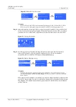
Figure F-1


Battery Status menu 


Status

: The battery status is 

NA

 (battery not connected or reversely connected), 

Equalized 

charging

Float charging

Hibernating

, or 

Discharging


Capacity

: indicates the remaining battery capacity. 


Backup time

: indicates the estimated discharge duration. The value is 

NA

 during battery charging. 

2.


Batteries in 

Hibernating

 state cannot start a capacity test. Choose 

Control

 and 

Maintain Batteries

, and then click 

Manual Float Charging

 to switch the batteries to 

the float charging state. Charge the batteries until the battery capacity reaches 100%. If 
the batteries hibernate due to a charger alarm, the batteries can switch between float 
charging and equalized charging only after the alarm is cleared. 

Summary of Contents for UPS2000-G-10 kVA

Page 1: ...UPS2000 G 6 kVA 20 kVA User Manual Issue 13 Date 2019 05 05 HUAWEI TECHNOLOGIES CO LTD ...

Page 2: ...stomer All or part of the products services and features described in this document may not be within the purchase scope or the usage scope Unless otherwise specified in the contract all statements information and recommendations in this document are provided AS IS without warranties guarantees or representations of any kind either express or implied The information in this document is subject to ...

Page 3: ...tallation Engineer Commissioning Engineer Data Configuration Engineer Maintenance Engineer Symbol Conventions The symbols that may be found in this document are defined as follows Symbol Description Indicates an imminently hazardous situation which if not avoided will result in death or serious injury Indicates a potentially hazardous situation which if not avoided could result in death or serious...

Page 4: ...sues are cumulative The latest document issue contains all the changes made in earlier issues Issue 13 2019 05 05 Updated the section Operating Environment Issue 12 2018 01 16 Added the description of device application scenarios Issue 11 2017 11 27 Updated the section Operating Environment Issue 10 2017 01 19 Added the DHCP feature Added an external dry contact card The default value of Max curre...

Page 5: ...e Optional Components Issue 04 2013 11 06 Added the description of Checking Before Powering On the UPS Issue 03 2013 08 24 Added the description of the UPS2000 G 15 kVA 20 kVA three phase input single phase output and single phase input single phase output Issue 02 2013 06 10 The software is upgraded Issue 01 2013 05 15 This is the first release ...

Page 6: ...rking Principle 11 2 2 1 Conceptual Diagram 11 2 2 2 Working Modes 11 2 3 Appearance 12 2 4 Optional Components 15 3 Installation 21 3 1 Preparations 21 3 1 1 Site 21 3 1 2 Tools 23 3 1 3 Power Cables 24 3 1 4 Unpacking and Checking 28 3 2 Installation Procedure 29 3 3 Installing a Backfeed Protection Device 29 3 3 1 Backfeed Protection Device Specifications 29 3 3 2 Feedback Prevention Connection...

Page 7: ...1 5 3 Parallel System Operations 72 5 3 1 Starting the Parallel System 73 5 3 2 Shutting down the Parallel System 76 5 3 3 Performing EPO 77 6 Communications 78 6 1 Optional Communications Components 78 6 2 SNMP Card 78 6 3 Modbus Card 79 6 4 Dry Contact Card 79 6 5 External Dry Contact Card 79 7 Routine Maintenance 80 7 1 UPS Maintenance 80 7 2 Battery Maintenance 81 8 Troubleshooting 86 9 Techni...

Page 8: ...opyright Huawei Technologies Co Ltd vii A Parallel Parameter List 100 B LCD Menus and Parameters 101 C Alarm Handling 111 D Alarm Handing of Battery Maintenance Notification 131 E Battery Shallow Discharge Test 133 F Capacity Test 136 G Acronyms and Abbreviations 139 ...

Page 9: ...the precautions and special safety instructions provided by Huawei when operating Huawei products Huawei will not be liable for any consequences that are caused due to violations regarding general safety regulations and equipment design production and usage safety standards Declaration Huawei does not take responsibilities for the following situations Operation under severe environments that are n...

Page 10: ...place or change the devices or components including software Operation personnel must report faults or errors that might cause serious safety issues to related owners This product should be installed and used according to the installation and technical specification requirements found in this manual Otherwise the product may be damaged and the resulting product exceptions or component damage will ...

Page 11: ... installation rack Ensure ventilation vents are unblocked while the system is operating Before powering on the device ensure that all the screws inside it are securely tightened and will not fall off during operation After the installation remove packing materials from the equipment area Replace danger signs that have worn out or are unreadable A UPS can be used to serve resistive capacitive loads...

Page 12: ...age currents Using a circuit breaker that has the leakage current protection function is not recommended The leakage current of the 6 kVA UPS is less than or equal to 100 mA The leakage current of the 10 kVA UPS is less than or equal to 200 mA The leakage current of the 15 kVA or 20 kVA UPS is less than or equal to 500 mA When selecting the earth leakage circuit breaker ELCB consider the leakage c...

Page 13: ...duct under areas prone to water leakage such as near air conditioner vents ventilation vents or feeder windows of the equipment room Ensure that there is no condensation inside the product or equipment room Ensure that no liquid enters the product Otherwise short circuits will occur and may result in serious injury or death If any liquid is detected inside the product immediately disconnect the po...

Page 14: ...device in an environment that has inflammable and explosive air or gas Do not perform any operation in this kind of environment If the valid mains voltage exceeds 320 V AC the UPS may be damaged Any operation on any electrical device in an environment that has inflammable air can cause extreme danger Strictly obey the operating environmental requirements specified in related use manuals when using...

Page 15: ...not reversely connect positive and negative battery terminals Use batteries of the specified type Otherwise the batteries may be damaged Check battery connections periodically to ensure that all screws are securely tightened Install or store batteries in clean cool and dry environments Do not decompose transform or damage batteries Otherwise battery short circuit electrolyte leakage and even perso...

Page 16: ...exceeds 60 C check the battery for electrolyte overflow If electrolyte overflows handle the leakage immediately Electrolyte Leakage In the case of electrolyte leakage counteract and absorb the leaking electrolyte immediately When moving or handling a battery whose electrolyte leaks note that the leaking electrolyte may harm human bodies If the electrolyte leaks use the following substances to coun...

Page 17: ...t strike or vibrations may damage the cable sheathing To ensure cable safety comply with the following requirements Cables can be laid or installed only when the temperature is higher than 0 C 32 F Handle cables with caution especially at lower temperatures Before laying out cables that have been stored in temperatures lower than 0 C 32 F move the cables to an environment that is at the requisite ...

Page 18: ...PS2000 G 6KRTL UPS2000 G 6 kVA long backup time model UPS2000 G 10KRTS UPS2000 G 10 kVA standard model The two models are represented by UPS2000 G 10 kVA in the description of their common features and parameters UPS2000 G 10KRTL UPS2000 G 10 kVA long backup time model UPS2000 G 15KRTL UPS2000 G 15 kVA The UPS2000 G 15KRTL has only a long backup time model UPS2000 G 20KRTL UPS2000 G 20 kVA The UPS...

Page 19: ...e RT rack and tower mounted unit RR rack mounted unit TT tower mounted unit TM modular tower mounted unit RM modular rack mounted unit 6 Built in battery optional S standard model which provides only a standard battery pack L long backup time model You need to use an external large capacity battery pack 2 2 Working Principle 2 2 1 Conceptual Diagram Figure 2 2 shows the UPS conceptual diagram Figu...

Page 20: ... overtemperature or faults occur This mode does not provide battery backup capability Economy control operation ECO mode If the bypass voltage and frequency are in the specified range the UPS supplies power to loads over the bypass If the bypass voltage and frequency are outside the range the UPS transfers to normal or battery mode ECO is short for economy control operation The UPS2000 G 15 kVA 20...

Page 21: ...kets 5 Parallel ports 6 Control area network CAN communications ports MON1 and MON2 7 Optional card slot 8 Battery temperature sensor port 9 Universal Serial Bus USB port 10 Emergency power off EPO port 11 Maintenance bypass port MBS 12 Fuse base 13 Input circuit breaker 14 Battery port The total load current supported by the two output sockets C13 cannot exceed 10 A The fuse used on the UPS2000 G...

Page 22: ...ure 2 4 Front and rear views of the UPS2000 G 10 kVA 1 Control panel 2 AC input ports 3 AC output ports pL and sL 4 Parallel ports 5 CAN communications ports MON1 and MON2 6 Optional card slot 7 Battery temperature sensor port 8 USB port 9 EPO port 10 Maintenance bypass port MBS 11 Input circuit breaker 12 Battery port ...

Page 23: ...15 kVA 20 kVA 1 Control panel 2 AC input ports mains and bypass 3 Battery terminals 4 EPO port 5 Maintenance bypass port MBS 6 Parallel ports 7 CAN communications ports MON1 and MON2 8 USB port 9 Battery temperature sensor port 10 Optional card slot 11 AC output ports pL and sL 2 4 Optional Components Table 2 2 Optional components Compone nt Model Function Remarks ...

Page 24: ...e Network Management Protocol SNMP card SNMP card RMS SNMP01A Monitors the UPS and the ambient temperatures and humidity if required and allows for Ethernet networking N A 6 kVA output isolation transformer box DGL 6 0 22 Provides isolation solutions for customer equipment Compared with the output transformer on an industrial frequency UPS the output transformer box provides isolation functions ev...

Page 25: ... RMS MODBUS01A Provides two cascaded RJ45 ports to implement networking over the Modbus or YDN 23 protocol N A Dry contact card RMS RELAY01A Provides six alarm dry contact outputs normal mode battery mode bypass mode low battery voltage bypass backfeed and UPS faults and two dry contract control inputs one is the shutdown signal input and the other is reserved N A External dry contact card RMS REL...

Page 26: ... parallel systems and implements online maintenance The PDU is designed for a 1 1 UPS2000 G 15 kVA 20 kVA parallel system three phase input three phase output PDU PDC 0091 V2ACIOA PDC 0091V2ACIOA The PDU is designed for a 1 1 UPS2000 G 15 kVA 20 kVA parallel system three phase input single phase output and single phase input single phase output It can also be used in a UPS2000 G 6 kVA 10 kVA 1 1 p...

Page 27: ... binding tape and secure them to the nearest place It is recommended that you install the battery temperature sensor secured with an adhesive on the surface of batteries in the middle of the battery rack In a UPS2000 G 15 kVA 20 kVA parallel system using the TN C power distribution system there are two scenarios for installing magnetic rings on the UPS mains input PE cables Figure 2 6 Installing m...

Page 28: ...l If you have directly grounded AC loads and battery packs and connected them to the UPS PE terminal install magnetic rings 2 and 3 on the PE3 PE4 PE5 and PE6 ground cables You need to purchase magnetic rings 2 and 3 The recommended type for magnetic rings 1 2 and 3 is DN85Hx4 or E2Fx4 Table 2 3 Specifications of magnetic rings from three vendors Vendor Magnetic Ring DMEGC R10K TDK HS10 TDG TS10 T...

Page 29: ...Environment Do not install the UPS in an environment outside the specifications Keep the UPS far away from water heat sources and flammable and explosive substances Install the UPS in an environment free of dust volatile gas salt and corrosive materials Avoid direct sunlight Do not install the UPS in environments with conductive metal scraps in the air The ideal operating temperature for batteries...

Page 30: ...sue 13 2019 05 05 Copyright Huawei Technologies Co Ltd 22 UPS2000 G 6 kVA 10 kVA Dimensions Figure 3 1 UPS2000 G 6 kVA 10 kVA installation dimensions UPS2000 G 15 kVA 20 kVA Dimensions Figure 3 2 UPS2000 G 15 kVA 20 kVA installation dimensions Clearances ...

Page 31: ...e of at least 500 mm respectively from the front and rear panels of the UPS to the wall or adjacent equipment to facilitate ventilation and heat dissipation as shown in Figure 3 3 Figure 3 3 Reserved clearances 3 1 2 Tools Get installation tools insulated to prevent electric shocks Table 3 1 lists the installation tools Table 3 1 Tools Tools Clamp meter Multimeter Label Phillips screwdriver PH 2 x...

Page 32: ...d 24 Tools Flat head screwdriver 2 mm x 80 mm Torque screwdriver Crimping tool Diagonal pliers Wire stripper Polyvinyl chloride PVC insulation tape Cotton cloth Brush Heat shrink tubing Heat gun Electrician s knife Protective gloves ESD gloves Insulated gloves Hydraulic pliers Cable tie 3 1 3 Power Cables ...

Page 33: ...2 and M6 OT terminals that are 90 bent and have a cross sectional area of 25 mm2 For 15 kVA 20 kVA model use battery ground cables that have a cross sectional area of 16 mm2 and M6 OT terminals that are 90 bent and have a cross sectional area of 16 mm2 For 6 kVA model use ground cables that have a cross sectional area of 6 mm2 and M4 OT terminals and have a cross sectional area of 6 mm2 For 10 kVA...

Page 34: ...A single pha se input single phas e output One mains input 1 220 V AC 230 V AC or 240 V AC 100 A the characte ristics of D 25 mm2 25 mm2 M6 OT terminal 4 8 N m Battery N A 240 V DC 63 A 16 mm2 16 mm2 M6 90 OT terminal 4 8 N m Output 1 220 V AC 230 V AC or 240 V AC 100 A the characte ristics of D 25 mm2 25 mm2 M6 OT terminal 4 8 N m 15 kVA three phas e input single phas e output Bypass input 1 220 ...

Page 35: ...63 A 16 mm2 16 mm2 M6 90 OT terminal 4 8 N m Output 3 380 V AC 400 V AC or 415 V AC 50 A the characte ristics of D 10 mm2 10 mm2 M6 OT terminal 2 8 N m 20 kVA single pha se input single phas e output One mains input 1 220 V AC 230 V AC or 240 V AC 125 A the characte ristics of D 25 mm2 25 mm2 M6 OT terminal 4 8 N m Battery NA 240 V DC 63 A 16 mm2 16 mm2 M6 90 OT terminal 4 8 N m Output 1 220 V AC ...

Page 36: ...nput 3 380 V AC 400 V AC or 415 V AC 63 A the characte ristics of D 10 mm2 10 mm2 M6 OT terminal 2 8 N m Mains input 3 Battery N A 240 V DC 63 A 16 mm2 16 mm2 M6 90 OT terminal 4 8 N m Output 3 380 V AC 400 V AC or 415 V AC 63 A the characte ristics of D 10 mm2 10 mm2 M6 OT terminal 2 8 N m If customers purchase input and output power cables by themselves use the cables that comply with standards ...

Page 37: ...e UPS in the installation position unpack it carefully to prevent scratches Procedure Step 1 Visually inspect the UPS appearance for shipping damage If any shipping damage is found report it to the carrier immediately Step 2 Move the UPS to the installation position Step 3 Unpack the case Step 4 Check the UPS packing 1 Check the UPS bar code which is at the rear panel of the UPS near the air exhau...

Page 38: ...a backfeed protection device on the input side Table 3 3 Rated voltages and currents for backfeed protection contactors Model Rated Voltage and Current Recommended Contactor Models Schneider contactors UPS2000 G 6KRTS 220 230 240 V AC 40 A LC1 D40A UPS2000 G 6KRTL UPS2000 G 10KRTS 220 230 240 V AC 65 A LC1 D50A for single phase input LC1 DT60A for three phase input UPS2000 G 10KRTL UPS2000 G 15KRT...

Page 39: ...1 3 3 2 Feedback Prevention Connections With Dry Contract Control Figure 3 5 Figure 3 6 Figure 3 7 and Figure 3 8 show backfeed protection connections with dry contract control Figure 3 5 Bypass backfeed protection connections for the UPS2000 G 6 kVA 10 kVA 15 kVA 20 kVA single phase input single phase output ...

Page 40: ...6 kVA 20 kVA User Manual 3 Installation Issue 13 2019 05 05 Copyright Huawei Technologies Co Ltd 32 Figure 3 6 Bypass backfeed protection connections for the UPS2000 G 10 kVA three phase input single phase output ...

Page 41: ...VA 20 kVA User Manual 3 Installation Issue 13 2019 05 05 Copyright Huawei Technologies Co Ltd 33 Figure 3 7 Bypass backfeed protection connections for the UPS2000 G 15 kVA 20 kVA three phase input three phase output ...

Page 42: ...kVA three phase input single phase output 3 4 Check After Installation Table 3 5 lists the check items Table 3 5 Post installation check items No Item Expected Result 1 Cable routing Cable routing meets engineering requirements 2 Cable connections Input cables output cables and battery cables are tightened to specified torques using a torque wrench connected correctly and free of damage ...

Page 43: ...neatly attached to both ends of each cable and the information on the labels is concise and understandable 5 Ground cable connection The ground cable is securely connected to the equipment room ground bar Measure the resistance between the UPS ground cable and the equipment room ground bar which must be less than 0 1 ohm 6 Distances between cable ties Distances between cable ties are the same and ...

Page 44: ...ntrols UPS running displays running data and allows you to set parameters and view alarms Figure 4 1 shows the control panel Figure 4 1 Control panel 1 Mains indicator 2 Battery indicator 3 Bypass indicator 4 Fault indicator INFO button 5 Startup Enter Battery Self Check Mute button 6 Down button 7 Up button 8 Shutdown Back button 4 2 Indicators Table 4 1 describes the indicators on the control pa...

Page 45: ... in ECO mode when the mains indicator and bypass indicator are both on 4 3 Functional Buttons The control panel provides five buttons to start and shut down the UPS and set parameters Table 4 2 describes the buttons Table 4 2 Button description Butt on Meaning Description ESC Shutdown Back On the default screen press ESC for more than 5 seconds Release the button when you hear a beep sound The inv...

Page 46: ...w the active alarm information When no alarm is generated press i to return to the default screen Battery self check After the UPS starts in normal mode it transfers to battery mode for 10 seconds to check that the battery status if no battery is connected No battery is displayed and that the UPS can transfer to battery mode The purpose is to prevent power backup failure when the UPS needs to tran...

Page 47: ...igure 4 2 shows a startup screen Figure 4 2 Description of the startup screen 1 Normal mode The solid line indicates normal mode The dotted line indicates non normal mode 2 Input voltage and frequency 3 Load power 4 Output voltage current and frequency 5 Bypass mode The solid line indicates bypass mode The dotted line indicates non bypass mode 6 Battery voltage and capacity displayed during charge...

Page 48: ...charging Battery discharging N A N A 4 5 1 Starting the UPS in Normal Mode Initial Startup The settings wizard starts automatically when you start the UPS for the first time or when you restart the UPS after restoring factory settings as shown in Figure 4 3 The settings wizard provides the Language System Parameters and Battery Parameters screens Figure 4 3 Settings wizard After you complete the s...

Page 49: ...d after non initial startup After the UPS starts it enters normal mode Figure 4 6 Normal mode Press The main menu screen is displayed 4 5 2 Starting the UPS in Battery Mode Initial Startup The settings wizard starts automatically when you start the UPS for the first time or when you restart the UPS after restoring factory settings The settings wizard provides the Language System Parameters and Bat...

Page 50: ...l startup Non initial Startup When the initialization is complete the standby screen is displayed Figure 4 8 Standby screen displayed after non initial startup After the UPS starts it enters battery mode Figure 4 9 Battery mode Press The main menu screen is displayed 4 6 LCD Menu Hierarchy Figure 4 10 Main Menu screen Figure 4 11 shows the LCD menu hierarchy ...

Page 51: ...UPS2000 G 6 kVA 20 kVA User Manual 4 Control Panel Issue 13 2019 05 05 Copyright Huawei Technologies Co Ltd 43 Figure 4 11 LCD menu hierarchy ...

Page 52: ...n the case of single phase input Frequency parameter Frequency displayed on the Mains Input screen Vab Vbc and Vca parameters Line voltages displayed on the Mains Input screen The parameters are not displayed in the case of single phase input Bypass Input Screen Figure 4 13 shows the Bypass Input screen Figure 4 13 Bypass Input screen Van Vbn and Vcn parameters Phase voltages displayed on the Bypa...

Page 53: ...attery not connected or reversely connected Equalized charging Float charging Hibernating or Discharging Capacity parameter Remaining battery capacity Backup time parameter Estimated backup time The value is NA during battery charge Inverter Output Screen Figure 4 15 shows the Inverter Output screen Figure 4 15 Inverter Output screen Van Vbn and Vcn parameters Phase voltages displayed on the Inver...

Page 54: ...put screen Local UPS Load Screen Figure 4 17 shows the Local UPS Load screen Figure 4 17 Local UPS Load screen Single UPS Running screen A single UPS is running Sout_A Sout_ B and Sout_C parameters Phase A B and C apparent power displayed on the Local UPS Load screen The parameter is Sout in the case of single phase input Pout_A Pout_ B and Pout_C parameters Phase A B and C active power displayed ...

Page 55: ...arallel System Load screen The parameter is Sys Sout in the case of single phase input the parameters are not displayed in single UPS mode Sys Pout_A Sys Pout_ B and Sys Pout_C parameters System phase A B and C active power displayed on the Parallel System Load screen The parameter is Sys Pout in the case of single phase input the parameters are not displayed in single UPS mode Sys Load ratio_A Sy...

Page 56: ... cabinet Runtime Screen Figure 4 20 shows the Runtime screen Figure 4 20 Runtime screen Inv runtime parameter Time during which the UPS runs in inverter output state BPS runtime parameter UPS bypass running duration 4 6 2 Alarms Screen On the Main Menu screen select Alarms and press The Alarms screen is displayed When the buzzer buzzes hold down for 2 5 seconds to mute it The buzzer is muted when ...

Page 57: ...nd name as shown in Figure 4 22 Figure 4 22 Historical Alarms screen Sort Alarms Screen The Sort Alarms screen allows you to view alarms by occurrence time or severity as shown in Figure 4 23 Figure 4 23 Sort Alarms screen Occurrence latest first parameter Alarms are sorted by occurrence time The latest alarms are listed first Level highest first parameter Active alarms are displayed by severity T...

Page 58: ... Co Ltd 50 Figure 4 24 Clear Alarms screen 4 6 3 Settings Screen On the Main Menu screen select Settings and press The Settings login screen is displayed The preset password is 000001 After you enter a password press The Settings screen is displayed as shown in Figure 4 25 Figure 4 25 Settings screen ...

Page 59: ...cted set the following parameters Figure 4 27 SNMP card settings IP alloc parameter Specifies the DHCP address allocating mode The options include Manual and Automatic The default value is Manual After the allocating mode is set to Automatic an Allocating dialog box is displayed on the screen If allocation succeeds the new IP address is displayed If allocation fails the IP address restores to the ...

Page 60: ...lue cannot be changed on the LCD 3 If a dry contact card is connected set the following parameters Figure 4 29 Dry contact card settings Multiple statuses can be associated with one dry contact but one status cannot be associated with multiple dry contacts Normal mode parameter Set the output dry contact associated with normal mode When the UPS is in normal or ECO mode this dry contact is enabled ...

Page 61: ...tem Parameters Screen Parallel screen Figure 4 30 Parallel screen Single Parallel parameter The values include Single and Parallel The default value is Single The parameter is configurable after the inverter shuts down Redundant UPSs parameter Set the number of redundant UPSs The value ranges from 0 to 3 The default value is 0 The parameter is configurable after the inverter shuts down Output scre...

Page 62: ...onfigurable after the inverter shuts down Volt adj coef parameter You can adjust the inverter rated output voltage The values include 5 4 3 2 1 and 0 default Press or to increase or decrease the output voltage The parameter is configurable after the inverter shuts down If you set Converter mode to Enabled the UPS cannot transfer to bypass mode or maintenance bypass mode If you shut down the invert...

Page 63: ...ude 0 5 Hz 1 Hz 2 Hz default 3 Hz 4 Hz 5 Hz and 6 Hz The parameter is configurable after the inverter shuts down ECO screen Figure 4 33 ECO screen You can use the ECO function only if power grid conditions are good and the voltage and frequency fluctuation is within the specified ECO voltage and frequency range Max voltage parameter Upper threshold for the ECO voltage In ECO mode when the differen...

Page 64: ...mode if the discharge time exceeds this value the UPS disconnects from secondary loads The value ranges from 0 Min to 999 Min in units of minutes The default value is 30 Min The parameter is configurable in non battery mode or non battery ECO mode The UPS2000 G 15 kVA 20 kVA supports battery ECO mode only in the case of two mains inputs In battery ECO mode the bypass supplies power to the UPS and ...

Page 65: ...e when the mains recovers The value ranges from 0S to 900S The default value is 5S The parameter is configurable after the inverter shuts down If Recovery delay time is set to 0S the actual recovery delay time is 1 second Max BPS transfers parameter Maximum number of bypass transfers within 30 minutes The value ranges from 1 to 3 The default value is 3 When the number of bypass transfers exceeds t...

Page 66: ... default value is Enabled If the value is Enabled UPS startup takes additional 30 180 seconds The parameter is configurable after the inverter shuts down Auto start parameter Determine whether to automatically start inverter output after the UPS connects to the mains The values include Disabled and Enabled The default value is Disabled The parameter is configurable after the inverter shuts down No...

Page 67: ...N is less than 20 the system output power is derated to N 20 in battery mode The parameter is configurable in non battery mode or non battery ECO mode You need to set Number of batteries on the UPS2000 G 6 kVA 10 kVA and set two battery strings positive and negative on the UPS2000 G 15 kVA 20 kVA Battery capacity parameter Set the battery string capacity The value ranges from 7 Ah to 1000 Ah For t...

Page 68: ... Voltage parameter Set the battery equalized voltage The value ranges from 2 33 V cell to 2 40 V cell The default value is 2 35 V cell The parameter is configurable in any mode Max current parameter Set the maximum equalized current On a standard model the value ranges from 1 0 A to 2 0 A and the default value is 2 0 A On a long backup time model the value ranges from 1 0 A to 4 0 A and the defaul...

Page 69: ...me to 0 hour the battery string may remain in the small current discharge state according to the proportion of the battery capacity to the load power which affects the battery lifecycle EOD mode parameter Determine the power backup time The values include Backup time first ensures system running and has a long backup time Table 4 5 shows the EOD setting values Batt protect first protects batteries...

Page 70: ... becomes normal The values include Disabled and Enabled The default value is Enabled The parameter is configurable after the inverter shuts down Shutdown delay parameter When the delay time reaches the value after UPS transfers to battery mode the UPS powers off The value ranges from 0S to 600S The default value is 0S The value interval is 30S For example the value can be 0S 30S 60S and 90S If the...

Page 71: ...l for shallow discharge tests The value ranges from 30Day to 90Day The default value is 60Day The parameter is configurable in any mode Discharge ratio parameter Set the proportion of the discharge capacity to the total discharge capacity The value ranges from 10 to 50 The default value is 20 The parameter is configurable in any mode Restoring Factory Settings You can restore factory settings afte...

Page 72: ...ter The parameter is configurable in non battery mode or non battery ECO mode Figure 4 44 Replace Batteries screen Maintain Batteries Menu Shallow Discharge Test menu Figure 4 45 Shallow Discharge Test screen Capacity Test menu After you completely discharge batteries the load ratio must be in the range of 20 80 Stop Test menu Figure 4 46 Stop Test screen Stop the shallow discharge test or capacit...

Page 73: ... Manual FC for Pos menu Figure 4 48 Manual FC for Pos screen Perform float charging on batteries forcibly For the 6 kVA and 10 kVA UPSs perform manual float charging For the 15 kVA and 20 kVA UPSs batteries in positive and negative groups are manually switched to float charging respectively Sync Paral Param Menu The menu allows you to synchronize the parameters from one UPS to the other UPSs in th...

Page 74: ...ntrol Buzzer is used for muting the alarm tone the alarm tone should be unmuted by using Control Buzzer or power on the UPS again Otherwise when a new alarm is generated it cannot buzz again If the buzzer off click Control Buzzer transfer to Buzzer on Figure 4 52 Buzzer on screen 4 6 5 About Screen On the Main Menu screen select About and press The About screen is displayed as shown in Figure 4 53...

Page 75: ...PS 10 kVA Model parameter The UPS model is 20K UPS ESN parameter This item provides the UPS ESN Version parameter This item provides the UPS version MU1MSW1 parameter This item provides the main monitoring software version PU1RSW1 parameter This item provides rectifier power software version PU1RSW2 parameter This item provides the rectifier logic software version PU1ISW1 parameter This item provi...

Page 76: ...circuit breakers and load circuit breakers are OFF Power cables and signal cables are correctly identified The input phase sequence is correct Cables are neatly routed and securely bound Devices are installed and cables are routed in ways that facilitate modification capacity expansion and maintenance Parallel cables are properly connected The UPS is properly grounded The voltage between the neutr...

Page 77: ...tage and frequency In the case of single phase output set Voltage level to 220 V default 230 V or 240 V in the case of three phase output set Voltage level to 380 V default 400 V or 415 V Battery parameters are configurable in non battery mode or non battery ECO mode Set Positive batteries and Negative batteries The value ranges from 16 to 20 The default value is 20 Set Battery capacity to the tot...

Page 78: ...evel and Frequency level are set based on the rated voltage and frequency Press ESC to return to the standby screen Step 4 Start the UPS in normal mode by using one of the following methods On the standby screen hold down more than 5 seconds Release the button when you hear a beep sound The startup screen is displayed If the UPS starts successfully it enters normal mode On the standby screen hold ...

Page 79: ...End 5 2 2 Shutting down the UPS Shutting down the Inverter To shut down the inverter perform any of the following operations On the default screen hold down ESC for more than 5 seconds Release the button when you hear a beep sound The inverter shuts down and the UPS transfers to bypass mode On the default screen press to enter the main menu Choose Shutdown to shut down the inverter The UPS transfe...

Page 80: ...an external switch to the EPO port on the UPS After you turn on the switch the inverter shuts down and the UPS will not transfer to bypass mode Output terminals completely power off which meets the EPO purpose The external EPO switch switch or dry contact signals controlled by a switch is provided by the customer 5 3 Parallel System Operations This section describes operations on a UPS2000 G 15 kV...

Page 81: ...input three phase output dual mains equipped with no PDU 5 3 1 Starting the Parallel System The configured number of batteries must match the actual number When the actual number changes change the configured number If the configured number is less than the actual number the battery lifespan is shortened If the configured number is greater than the actual number battery leakage may cause a fire ...

Page 82: ...s Km1 and Km2 general mains input circuit breaker Km bypass input circuit breakers Kb1 and Kb2 general bypass input circuit breaker Kb and UPS AC output circuit breakers Q1 and Q2 The initialization screen is displayed The parallel system supplies no power Perform Step 2 when there are two mains inputs In the case of one mains input you need only to close the UPS mains input circuit breakers and g...

Page 83: ...ry cables Step 2 Close the AC output circuit breakers Q1 and Q2 for the parallel system Step 3 Press on each control panel The initialization screen is displayed on each LCD On the standby screen press to enter the main menu Choose Main Menu Settings System Parameters Output to view output settings if the system uses three phase input three phase output Output mode is set to Three phase if the sys...

Page 84: ...ans stop the UPS shuts down Step 3 Open the external battery circuit breaker if there is or disconnect battery cables The UPS exits the parallel system To merely shut down the UPS perform Step 1 only End Transferring the Parallel System to Bypass Mode Perform shutdown operations on each UPS in the parallel system All inverters shut down at the same time and the parallel system transfers to bypass ...

Page 85: ... by the customer The parallel system enters the EPO state That is the inverters shut down and the parallel system will not transfer to bypass mode Figure 5 4 shows the EPO cable connection in a parallel system Figure 5 4 EPO cable connection in a parallel system Connect an external switch to the EPO port on the UPS After you turn on the switch the UPS stops inverter output and does not transfer to...

Page 86: ...l system management using only one SNMP card Adapts to the 10 Mbit s 100 Mbit s fast Ethernet FE by using an IP address that is configurable on the LCD Supports SNMP Hypertext Transfer Protocol Secure HTTPS and Secure Shell SSH Supports SNMP agent v1 v2c and v3 The UPS MIB library can be downloaded from its own web page instead of any CD ROM Enables remote management on Windows or Linux using a we...

Page 87: ...switch to select a two wire or four wire system Provides a DIP switch to select a build out resistor Provides a DIP switch for setting the optional card address Supports hot swap 6 4 Dry Contact Card The RMS RELAY01A is installed in an optional card slot and supports hot swap The dry contact card provides six alarm dry contact outputs normal mode battery mode bypass mode low battery voltage bypass...

Page 88: ...form maintenance Maintain UPSs regularly based on the following requirements Otherwise the UPSs may fail to operate properly and the lifespan may be shortened Table 7 1 Routine maintenance items for UPSs Check Item Expected Result Troubleshooting Maintenance Interval Operating environment Ambient temperature 0 40 C Humidity 0 95 RH non condensing If the humidity and temperature are abnormal check ...

Page 89: ...number of batteries and the actual battery capacity Reset the parameters Quarterly Power cables and terminals between the UPS and the power distribution cabinet The insulation layers of cables are intact and terminals are free from noticeable sparks Replace the cables Secure the output terminals Quarterly EPO if configured Check the reliability of the EPO cable connection Secure the terminals Year...

Page 90: ...ies have not been discharged for a long time discharge and charge them in equalized mode at least once every three months to activate them Each charge should last at least 4 hours Normally discharge and charge batteries once every four to six months Each charge should last at least 4 hours In high temperature areas discharge and charge batteries once every two months Each charge should last at lea...

Page 91: ...y string Equalized voltage 14 1 V x Number of batteries tolerance 1 Float voltage 13 5 V x Number of batteries tolerance 1 1 If the voltage drop between the battery string output terminals and the battery input terminals at the UPS side is greater than 1 of the battery string voltage check whether the cable between the battery string and the UPS is excessively long or the cable diameter is excessi...

Page 92: ... layer does not crack Replace the faulty cable Quarterly Battery volta Equalized charging voltage 14 1 V 0 1 V Float charging voltage 13 5 V 0 1 V 1 Check whether the equalized charging voltage and float charging voltage of a battery are normal 2 If the charging voltage of a battery exceeds the specifications requirement perform a complete forcible equalized charging for the battery and check agai...

Page 93: ...attery connection reliability 1 Each battery terminal is connected reliably When battery strings are powered off check the reliability of each terminal in the order from positive terminals to negative terminals 2 The tightening torque of each battery screw meets the requirements of the battery manufacturer A torque wrench is used for checking the torque After checking that the battery screws meet ...

Page 94: ... is not connected Check the input power cable connection The input voltage exceeds the limit Use a multimeter to check that the UPS input voltage meets specifications 2 The mains is normal but the AC input indicator is off The UPS runs in battery mode The mains switch is OFF Turn on the mains switch The input power cable is not securely connected Check the input power cable connection 3 The UPS do...

Page 95: ...Shut down the UPS immediately and cut off the input power supply Contact local Huawei technical support 8 The battery indicator is blinking yellow The buzzer buzzes 1 second and then stops 1 second The battery capacity is insufficient The UPS is shutting down The remaining battery capacity is insufficient The UPS is shutting down and the loads are powering off Parameters settings of battery number...

Page 96: ...m x 615 mm 430 mm x 130 mm x 757 mm Weight 14 kg 16 kg 32 kg 32 kg 9 2 Environmental Specifications Table 9 2 Environmental specifications Item 6 kVA 10 kVA 15 kVA 20 kVA Operating temperature 0 40 C Humidity 0 95 RH non condensing Altitude 1000 meters When the altitude is 1000 4000 meters see IEC62040 3 to check how the UPS power is derated The output power derating by 1 for each additional 100 m...

Page 97: ...ut 220 V AC 230 V AC or 240 V AC single phase input 380 V AC 400 V AC or 415 V AC three phase input Input voltage 80 280 V AC When the voltage is 80 176 V AC the load power is linearly derated to 40 100 80 280 V AC single phase When the voltage is 80 176 V AC the load power is linearly derated to 40 100 138 485 V AC three phase When the voltage is 138 305 V AC the load power is linearly derated to...

Page 98: ...20 kVA Bypass voltage Upper threshold 10 15 20 25 220 V AC Upper threshold 10 15 20 230 V AC Upper threshold 10 15 240 V AC Lower threshold 10 20 30 40 50 60 Bypass frequency tolerance Maximum 6 Hz configurable on the LCD Bypass overload capability Load 125 continuous in bypass mode 125 load 150 1 minute in bypass mode Load 150 100 milliseconds in bypass mode The input switch may trip in advance I...

Page 99: ... factor A maximum of 3 1 Inverter overload capability 105 load 125 transfer to bypass mode after 5 minutes 125 load 150 transfer to bypass mode after 1 minute Load 150 transfer to bypass mode after 100 milliseconds The UPS stops supplying power if the bypass is abnormal Dynamic voltage tolerance 5 Output voltage unbalance N A 1 balanced load 3 unbalanced load Average frequency tracking rate 0 5 2 ...

Page 100: ...rs battery discharge protection is not implemented The single battery voltage drops below 10 8 V in normal mode Standard UPS battery type 12 V DC VRLA battery Standard UPS battery capacity 7 Ah 9 Ah N A N A Backup time 4 minutes at full rated load Figure 9 1 Figure 9 2 Figure 9 3 and Figure 9 4 show the battery pack backup time Parallel feature Batter strings can be connected in parallel If the us...

Page 101: ...battery pack used first The ESS 240V12 7AhBPVBA01 part number is 02310PFD The ESS 240V12 9AhBPVBA01part number is 02310MWN Table 9 7 Backup time parameters for the ESS 240V12 7AhBPVBA01 battery pack 6 kVA battery efficiency assumed as 94 Load Load W One Battery pack min Two Battery packs min Three Battery packs min Four Battery packs min 100 5400 6 19 29 46 80 4320 9 25 43 57 50 2700 19 46 68 92 3...

Page 102: ...arameters for the ESS 240V12 7AhBPVBA01 battery pack 6 kVA battery efficiency assumed as 94 Table 9 8 Backup time parameters for the ESS 240V12 9AhBPVBA01 battery pack 10 kVA battery efficiency assumed as 94 Load Load W One Battery pack min Two Battery packs min Three Battery packs min Four Battery packs min 100 9000 4 12 23 32 80 7200 7 17 29 44 ...

Page 103: ...t Huawei Technologies Co Ltd 95 Load Load W One Battery pack min Two Battery packs min Three Battery packs min Four Battery packs min 50 4500 12 32 53 70 30 2700 26 57 88 125 Figure 9 2 Backup time parameters for the ESS 240V12 9AhBPVBA01 battery pack 10 kVA battery efficiency assumed as 94 ...

Page 104: ... Co Ltd 96 Table 9 9 Backup time parameters for the ESS 240V12 9AhBPVBA01 battery pack 15 kVA battery efficiency assumed as 94 Load Load W Two Battery packs min Four Battery packs min Six Battery packs min Eight Battery packs min 100 13500 7 19 32 48 80 10800 9 26 44 57 50 6750 18 48 70 96 30 4050 35 79 125 171 ...

Page 105: ...meters for the ESS 240V12 9AhBPVBA01 battery pack 15 kVA battery efficiency assumed as 94 Table 9 10 Backup time parameters for the ESS 240V12 9AhBPVBA01 battery pack 20 kVA battery efficiency assumed as 94 Load Load W Two Battery packs min Four Battery packs min Six Battery packs min Eight Battery packs min 100 18000 4 12 23 32 80 14400 7 17 29 44 ...

Page 106: ...t Huawei Technologies Co Ltd 98 Load Load W Two Battery packs min Four Battery packs min Six Battery packs min Eight Battery packs min 50 9000 12 32 53 70 30 5400 26 57 88 125 Figure 9 4 Backup time parameters for the ESS 240V12 9AhBPVBA01 battery pack 20 kVA battery efficiency assumed as 94 ...

Page 107: ...n parallel 4 The UPS2000 G 15 kVA 20 kVA single phase input single phase output supports 3 1 parallel systems at most instead of 4 0 parallel systems 9 9 Safety Regulations and EMC Table 9 13 Safety regulations and EMC Item Standards Compliance Remarks Electromagn etic compatibilit y Conducted radiation IEC EN62040 2 N A Voltage change fluctuations and flicker I 16 A IEC EN61000 3 3 16 A I 75 A IE...

Page 108: ...l Yes ECO max voltage Yes Volt adj coef Yes ECO min voltage Yes Frequency level Yes Output mode Yes ECO enabled Yes Auto check bus capa Yes Output transformer Yes Auto start Yes Recovery delay time Yes Bypass max voltage Yes Bypass frequency range Yes Bypass min voltage Yes Self load output power ratio Yes Generator mode Yes Max BPS transfers Yes EOD auto start Yes Converter mode Yes Self load mod...

Page 109: ...1 B LCD Menus and Parameters Main Menu Second Level Menu Third Level Menu Fourth Level Menu Value Range Preset Value Status Mains Input Van N A N A N A Vbn Vcn Frequency Vab Vbc Vca Bypass Input Van Vbn Vcn Frequency Battery Status Battery voltage Batte ry current Status Capacity Backup time Inverter Output Van Ia Vbn Ib ...

Page 110: ...hird Level Menu Fourth Level Menu Value Range Preset Value Vcn Ic Frequency UPS Output Van Ia Vbn Ib Vcn Ic Frequency Local UP S Load Single UPS Running N X Parallel Syst em Sout_A Pout_A Load ratio_A Sout_B Pout_B Load ratio_B Sout_C Pout_C Load ratio_C Parallel System Load Single UPS Running N X Parallel Syst em Sys Sout_A Sys Pout_A Sys Load ratio_A ...

Page 111: ...i ng Ambient temp Ambient humidity Internal temp Runtime Inv runtime BPS runtime Alarms Active Alarms Active alarms Details N A N A Historica l Alarms Historical alarms Details Sort Alarms Occurrence latest first N A Level highest first Clear Alarms N A Setting s Basic Settings Language N A English Chinese Turkish French and Russian English Change Password N A 000000 999999 000001 Change Feature C...

Page 112: ... Dry contact 1 6 Dry contact 2 Bypass mode Dry contact N A Dry contact 1 6 Dry contact 3 Batt undervolt Dry contact N A Dry contact 1 6 Dry contact 4 BPS backfeed Dry contact N A Dry contact 1 6 Dry contact 5 Faulty UPS Dry contact N A Dry contact 1 6 Dry contact 6 System Paramete rs Parallel configurable after the inverter shuts down Single Parallel Single and Parallel Single Redundant UPSs 0 3 0...

Page 113: ... adj coef 5 4 3 2 1 and 0 0 Converter mode Enabled and Disabled Disabled Bypass configurable after the inverter shuts down Max voltage 10 15 20 25 and 30 15 Min voltage 10 20 30 40 50 and 60 20 Frequency range 0 5 Hz 1 Hz 2 Hz 3 Hz 4 Hz 5 Hz and 6 Hz 2 Hz ECO configurable after the inverter shuts down Max voltage 5 6 7 8 9 and 10 10 Min voltage 5 6 7 8 9 and 10 10 Frequency range 0 5 Hz 1 Hz 2 Hz ...

Page 114: ... Enabled and Disabled Disabled Generator mode Weak adaptability mode Balanced mode and Strong adaptability mode Balanced mode Auto check capa Enabled and Disabled Enabled Auto start Enabled and Disabled Disabled No battery alarm configurable only when batteries are not connected Enabled and Disabled Enabled Battery Paramete rs Basic Batteries Positive batteries Negati ve batteries configurable in ...

Page 115: ...odel 4 0 8 0 A long backup time model 3 0 A standard model 6 0 A long backup time model Equalized Charge Equalized charging Enabled and Disabled Enabled Time interval 30 180 days 60 Day Voltage 2 33 2 40 V cell 2 35 V cell Max current 1 0 2 0 A standard model 1 0 4 0 A long backup time model 2 0 A Max time 600 999 minutes 960 Min Float Charge Voltage 2 25 2 30 V cell 2 25 V cell Temp comp coef 0 0...

Page 116: ...ltage level 220 V 230 V and 240 V on the UPS2000 G 6 kVA 10 kVA 220 V 230 V and 240 V single phase on the UPS2000 G 15 kVA 20 kVA 380 V 400 V and 415 V three phase on the UPS2000 G 15 kVA 20 kVA 220 V on the UPS2000 G 6 kVA 10 kVA 220 V single phase on the UPS2000 G 15 kVA 20 kVA 380 V three phase on the UPS2000 G 15 kVA 20 kVA Frequency level 50 Hz 60 Hz and Automatic 50 Hz Output mode configurab...

Page 117: ...h on a standard model and 65 Ah on a long backup time model For the UPS2000 G 15 kVA 20 kVA the default value is 65 Ah on a long backup time model Restore Default Settings configur able after the inverter shuts down N A N A N A N A Contro l Startup N A N A N A N A Shutdow n Replace Batteries Maintain Batteries Shallow Discharge Test Capacity Test Stop Test Manual Equalized Charging Ma nual EC for ...

Page 118: ...er than or equal to the current ECO frequency range if the ECO frequency range is 3 Hz the bypass frequency range is 3 Hz 4 Hz 5 Hz or 6 Hz The ECO frequency range must be less than or equal to the current bypass frequency range if the bypass frequency range is 1 Hz the ECO frequency range is 0 5 Hz or 1 Hz The voltage level is associated with the upper threshold for bypass voltages 10 15 20 25 or...

Page 119: ...Hz Measures Check whether the mains input voltage is less than 272 V If not wait until the mains recovers Check whether the mains input voltage is greater than 88 V If not wait until the mains recovers Check the mains input frequency If the mains input frequency is abnormal wait until the mains input recovers 0001 02 Abnorma l mains volt Minor 0001 03 Abnorma l mains volt Minor 0004 01 Mains phase...

Page 120: ... UPS has transferred from normal mode to battery mode within 2 minutes for 10 consecutive times The rectifier locks out in battery mode Measure Check the mains 0008 01 Rect start overlimit Minor Manual clear Po wer off clear The UPS cannot start Possible cause The mains voltage frequently becomes abnormal during startup Measure Check the mains input voltage If the voltage becomes normal clear the ...

Page 121: ...rter has started the inverter still works properly but the system cannot transfer to bypass mode Possible cause The bypass input neutral wire is not connected Measures Check that bypass input power cables are correctly connected 0014 01 Start timeout Critical Manual clear Po wer off clear The UPS cannot start Possible causes The bypass load exceeds the rated inverter load An internal fault occurs ...

Page 122: ...25 01 Batt overvolt Minor Automati c clear An alarm is generated and the battery lifespan is affected Possible causes The configured number of batteries is less than the actual number The battery string charge voltage exceeds the upper threshold Measures Check battery parameter settings Disconnected the external battery charger check whether the alarm is cleared If not contact Huawei technical sup...

Page 123: ...mati c clear N A Possible causes The bypass is short circuited or the bypass input experiences overcurrent The bypass input circuit breaker is OFF Measures Check whether the bypass output load is short circuited using a multimeter Check whether cable connections are correct If yes switch on the bypass input circuit breaker 0028 03 Breaker OFF Critical Automati c clear N A Possible causes The bypas...

Page 124: ...Minor Automati c clear The power supply from the UPS and system is not affected Possible causes The ambient temperature exceeds 40 C The air channel is blocked The fan is abnormal Measures Decrease the ambient temperature Keep the air intake and exhaust vents of the UPS unobstructed Clean off the foreign objects around the fan If the alarm persists contact Huawei technical support for repair 0032 ...

Page 125: ...onfigured battery capacity 0036 01 Batt maint notif Minor Automati c clear An alarm is generated If the shallow discharge test is not performed for a long time the battery power backup function may be affected Possible cause The battery does not experience shallow discharge and the maintenance period expires Measure Perform the following steps Click the alarm The battery maintenance menu is displa...

Page 126: ...re is damaged Measures After you rectify the fault restart the UPS Check whether the load type is supported by the UPS Enable the transformer mode Contact Huawei technical support for repair 0040 05 Rectifier fault Critical Manual clear Po wer off clear Aut omatic clear The UPS shuts down The UPS transfers to another working mode or shuts down Possible cause The hardware is damaged Measure Contact...

Page 127: ...10 Rectifier fault Critical Manual clear Po wer off clear The UPS shuts down Possible cause The digital signal processing DSP or complex programmable logical device CPLD chip is faulty Measure Contact Huawei technical support for repair 0041 01 Rectifier alarm Minor Manual clear Po wer off clear N A Possible cause The EEPROM chip is faulty Measure Contact Huawei technical support for repair 0041 0...

Page 128: ...9 Internal fault Critical Automati c clear The inverter shuts down Possible cause Self load cable connections are incorrect Measure Reconnect cables 0042 10 Internal fault Critical Automati c clear If the inverter has not started the UPS has no output and inverter startup is not allowed If the inverter has started inverter operation is not affected but transfer to bypass mode is not allowed Possib...

Page 129: ...d the fan If the alarm persists contact Huawei technical support for repair 0043 06 Fan fault Critical Automati c clear The power supply from the UPS and system is not affected Possible cause The fan is abnormal Measure Clean off the foreign objects around the fan If the alarm persists contact Huawei technical support for repair 0044 01 Incompat ible ver Critical Manual clear Po wer off clear The ...

Page 130: ...lear Po wer off clear The charger in the UPS stops Possible cause The charger capacitor is faulty Measure Contact Huawei technical support for repair 0045 04 Charger alarm Critical Possible cause The charger output is short circuited Measure Rectify battery port short circuits After you clear the alarm restart the UPS If the alarm persists contact Huawei technical support for repair 0045 06 Charge...

Page 131: ...inverter shuts down The UPS transfers to bypass mode or has no output based on the transfer logic Possible cause The inverter is faulty Measure Contact Huawei technical support for repair 0060 02 Inverter fault Critical Power of f clear The UPS shuts down The UPS may transfer to another working mode or shut down Possible cause The inverter relay is faulty Measure Contact Huawei technical support f...

Page 132: ...temperature exceeds 40º C The air channel is blocked The fan is abnormal Measures Decrease the ambient temperature Keep the air intake and exhaust vents of the UPS unobstructed Clean off the foreign objects around the fan If the alarm persists contact Huawei technical support for repair 0060 08 Inverter fault Critical Manual clear Po wer off clear The UPS shuts down Possible cause The DSP or CPLD ...

Page 133: ... or replace the UPS with a larger capacity UPS 0065 01 Power segment Minor Manual clear Po wer off clear In single UPS mode the loads connected to pL power off Possible cause The load exceeds the rated loading capacity Measure Reduce the load or replace the UPS with a larger capacity UPS 0065 02 Power segment Minor Automati c clear Ma nual clear Possible causes The battery voltage is below the bat...

Page 134: ...Manual clear Po wer off clear The UPS shuts down The parallel system shuts down Possible causes The parallel cable is loose The parallel cable is damaged Measures Check that the parallel cable is securely connected Replace the parallel cable Contact Huawei technical support for repair 0083 02 Paral cable fault Critical 0083 04 Paral cable fault Critical Manual clear Po wer off clear Aut omatic cle...

Page 135: ...n the parallel system Measures Reduce the number of redundant UPSs or set the system to be non redundant Reduce the load or replace the UPS with a larger capacity UPS 0096 01 Abnorma l ECO volt Minor Automati c clear Transfer to bypass mode is prohibited If the bypass is supplying power the UPS transfers to another working mode Possible cause The ECO input is abnormal Measure Check whether the ECO...

Page 136: ...t overtemp erature Minor Automati c clear An alarm is generated Possible causes The ambient temperature in the UPS equipment room exceeds the alarm threshold default value 40 C The temperature and humidity transducer is faulty Measures Check the ambient temperature in the UPS equipment room Replace the temperature and humidity transducer 0133 01 Ambient undertem perature Minor Possible causes The ...

Page 137: ...he ambient humidity of the UPS equipment room Replace the temperature and humidity transducer 0136 01 Faulty temperat ure and humidity module Minor Possible causes The temperature and humidity module is faulty Measures Check parameter settings of the temperature and humidity transducer Replace the temperature and humidity transducer 0158 01 On bypass Minor Automati c clear If the bypass is abnorma...

Page 138: ...l wait until the mains input recovers Check whether the UPS is in battery self check state Reduce the load or replace the UPS with a larger capacity UPS 0340 01 Maint breaker ON Minor Automati c clear The UPS transfers to bypass mode Possible cause The maintenance circuit breaker is ON during UPS maintenance Measure Switch off the maintenance circuit breaker after maintenance 61440 0 1 Flash fault...

Page 139: ...nfo key are blinking red and alarms are generated intermittently Procedure Step 1 Clear the Batt maint notif alarm 1 Press the i key on the UPS control panel to display the Active Alarms page If multiple active alarms exist use the or key to select the alarm record on the top the latest alarm is on the top by default Press to view the alarm ID and name Figure D 1 Viewing alarms 2 Press to display ...

Page 140: ...t the battery maintenance notification 0036 01 to appear again perform the following steps 1 On the Main Menu screen select Settings and press The Settings login screen is displayed The preset password is 000001 After you enter the correct password and press the Settings screen is displayed 2 Choose Battery Parameters and Shallow Discharge and then change the value of Test notification from Enable...

Page 141: ...tus screen locate Battery Status Figure E 1 Battery Status menu Status The battery status is NA battery not connected or reversely connected Equalized charging Float charging Hibernating or Discharging Capacity indicates the remaining battery capacity Backup time indicates the estimated discharge duration The value is NA during battery charging 2 Batteries in Hibernating state cannot start a shall...

Page 142: ...ischarge screen Discharge ratio indicates the percentage of discharge capacity to the total dischargeable capacity The parameter can be set to a value between 10 and 50 and the default value is 20 The parameter is configurable in any mode It is recommended that the value of Discharge ratio not exceed 20 with the load is light For example the value can be 10 or 15 Step 3 Start the shallow discharge...

Page 143: ...UPS2000 G 6 kVA 20 kVA User Manual E Battery Shallow Discharge Test Issue 13 2019 05 05 Copyright Huawei Technologies Co Ltd 135 Figure E 5 Stop Test screen End ...

Page 144: ...atus menu Status The battery status is NA battery not connected or reversely connected Equalized charging Float charging Hibernating or Discharging Capacity indicates the remaining battery capacity Backup time indicates the estimated discharge duration The value is NA during battery charging 2 Batteries in Hibernating state cannot start a capacity test Choose Control and Maintain Batteries and the...

Page 145: ...Figure F 3 Viewing the load rate Step 3 Start the capacity Test Partially discharge the batteries and ensure that the load rate is between 20 and 80 After all required conditions are met the test command is successfully delivered and the LCD displays a Succeeded message Figure F 4 Shallow Discharge screen If the load rate and battery capacity do not meet the requirements the system displays a mess...

Page 146: ...kVA User Manual F Capacity Test Issue 13 2019 05 05 Copyright Huawei Technologies Co Ltd 138 Figure F 5 Load not met Figure F 6 Batt not fully charged Step 4 Stop the capacity Test forcibly Figure F 7 Stop Test screen End ...

Page 147: ...twork CPLD complex programmable logical device D DIP dual in line package DOD depth of discharge DSP digital signal processing E EPO emergency power off ECO economy control operation EOD end of discharge ESD electrostatic discharge ESN equipment serial number H HTTPS Hypertext Transfer Protocol Secure L LCD liquid crystal display LSI large scale integrated M MIB management information base N NMS n...

Page 148: ...ive earthing PL parallel load PVC polyvinyl chloride R RS232 Recommend Standard 232 RS485 Recommend Standard 485 S SELV safety extra low voltage SNMP Simple Network Management Protocol T THDv total harmonic distortion of output voltage TNV telecommunication network voltage U UPS uninterruptible power system USB Universal Serial Bus V VRLA valve regulated lead acid ...

Reviews: