12
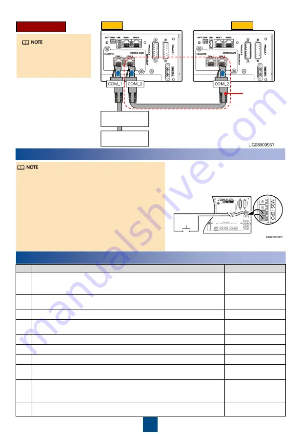
Modbus Card
In the figure, the two
UPSs represent two
standalone UPS
systems.
5
(Optional) Connecting an EPO Switch
1. For UPS2000-G-15KRTL-01/UPS2000-G-20KRTL-
01, choose Settings > System Parameters >
Other Settings and set EPO Enable to Enable.
2. Connect an external switch to the EPO ports of
the UPS. After you turn on the switch in the case
of emergency, the inverter stops and the UPS
does not transfer to bypass mode. In this way,
the UPS stops supplying power immediately.
3. The customer provides the external switch (it can
be a common switch) that connects to the EPO
ports.
6
Verifying the Installation
No.
Item
Result
1
If the input or output system is changed, ensure that the short-circuit
copper bar status and cable connections at input and output ports are
correct.
□
Passed
□
Failed
2
The phase sequence of the input power is correct. Use a multimeter to
check that the input and output are not short-circuited.
□
Passed
□
Failed
3
Cables and terminals are securely connected.
□
Passed
□
Failed
4
Battery cables and terminals are connected correctly, and voltages
comply with industry standards.
□
Passed
□
Failed
5
The UPS is properly connected to battery strings.
□
Passed
□
Failed
6
Input circuit breakers and load circuit breakers are OFF.
□
Passed
□
Failed
7
Power cables and signal cables are correctly identified.
□
Passed
□
Failed
8
The ground cable is reliably connected. The voltage difference
between the neutral wire and the ground cable is less than 5 V AC.
□
Passed
□
Failed
9
The mains input voltage is 120–280 V AC during power-on (80–280 V
AC after power-on).
□
Passed
□
Failed
10
The positive and negative battery voltages range from 200 V DC to
280 V DC (measured using a multimeter).
□
Passed
□
Failed
Modbus card
cascading
UPS 1
UPS 2
RS232-RS485
adapter
RS232 port
on the PC


