background image

9

5

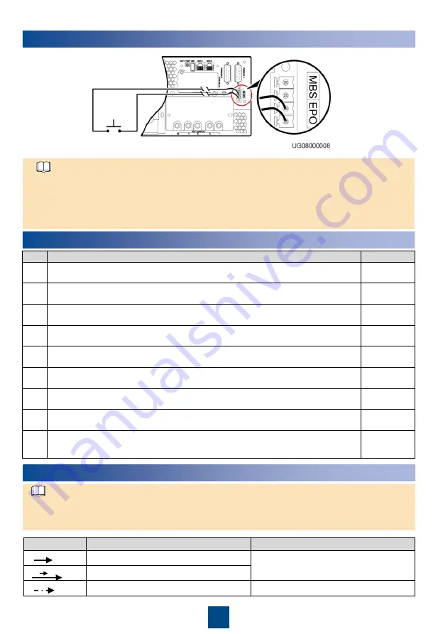
(Optional) Connecting Cables to EPO Port

NOTE

1. Connect  an external  switch to the EPO ports. One second  after you turn on the switch, which 

means  that terminals  1 and 2 are short-circuited, the inverter stops, and the bypass mode is 
disabled. In this way, the UPS  stops supplying  power immediately.

2. The customer provides  the external  switch (it can be a common  switch) that connects  to EPO 

ports.

6

Verifying the Installation

No.

Item

Result

1

If the input  or output  system changes,  ensure  the correct short-circuit copper bar 
status and  cable connections  are applied  to the input  and output  ports.

Passed 

Failed

2

The input  phase sequence  is correct. Use a multimeter  to check that the input 
and output  are not short-circuited.

Passed 

Failed

3

Cables and terminals  are securely connected.

Passed 

Failed

4

Battery cables and terminals  are connected  correctly, and voltages  comply with 
industry  standards.

Passed 

Failed

5

The UPS  is properly connected  to battery strings.

Passed 

Failed

6

Input  circuit breakers and  load circuit breakers are OFF.

Passed 

Failed

7

Power cables and  signal  cables are correctly identified.

Passed 

Failed

8

Ground  cables are firmly connected.  The voltage  difference between a neutral 
wire and  a ground  cable is less than  5 V AC.

Passed 

Failed

9

The mains  supply  voltage  is 73

–144 V AC during  power-on (73–144 V AC after 

power-on). The battery voltage  is greater than  46.5 V DC.

Passed 

Failed

Symbol

Description

Remarks

Press A.

A and B indicate  operation  symbols on 
the control panel.

Press A and then  B.

Indicates omitted screens.

N/A

A

A

B

7

Powering On and Starting the UPS

User interface (UI) snapshots  shown  in this document  correspond to V200R001C91SPC070  and 
are for reference only. If any UI changes  are made, contact Huawei  technical  support to obtain 
the latest snapshots.

NOTE

Summary of Contents for UPS2000-G-3K-V1-DR

Page 1: ...ormal mode Off The UPS is not working in normal mode 3 Battery indicator On The UPS is in battery mode Off The UPS is not in battery mode Blinking The remaining battery capacity is less than 25 4 Bypass indicator On The UPS is in bypass mode Off The UPS is not in bypass mode 5 Fault indicator INFO button Steady red The UPS is faulty Blinking red The UPS generates an alarm Green The UPS is running ...

Page 2: ...urity protection mechanism supported 6 Control area network CAN communications ports 7 Parallel ports 8 Maintenance bypass port 9 Emergency power off EPO port 1 ESM dry contact output DO1 DO2 2 Communications port COM_ IN 3 Communications port COM_ OUT 4 Protective ground GND 5 Indicators 6 Button for manual power on off MANUAL ON OFF 7 ESMU port for connecting to an external power source PWR 8 Po...

Page 3: ...ing at 0 5 Hz The communication between the rectifier and the external equipmentis interrupted Fault indicator Red Steady on The rectifier locks out due to output overvoltage The rectifier has no output due to an internal fault Off The rectifier is running properly Rectifier in the PDU Silk Screen Indicator Color Status Description RUN Running indicator Green Steady on Communication is normal incl...

Page 4: ...unting brackets for the UPS 1 Before installation read the user manual carefully to get familiar with product information and safety precautions 2 Use insulated tools during installation 3 Only engineers certified by Huawei or its agents are allowed to install commission and maintain the UPS Otherwise personal injury or equipment damage may occur and the UPS faults caused are beyond the warranty s...

Page 5: ...e power off 3 When the AC input or AC output changed for details about how to change the input or output system contact Huawei technical support Do not power on the UPS directly 4 Connect the UPS output power cable to the AC OUTPUT sL terminal 4 Insert the rectifier into the PDU lock the locking latch of the rectifier and install the PDU on the rack c Install guide rails based on the actual situat...

Page 6: ...l the UPS output short circuit copper bar 2 Install cables AC output power cable AC input power cable PDU rear UPS rear Battery front UPS CAN Battery CAN Battery cable UPS input cable UPS output cable Battery cable Battery cable Battery CAN 1 2 3 4 5 7 8 9 10 11 12 13 6 ...

Page 7: ...7 Battery cable 8 UPS CAN communications cable Ethernet cable RJ45 terminal Provided by Huawei 9 Battery CAN communications cable Ethernet cable RJ45 terminal Provided by Huawei 10 Battery CAN communications cable 11 PDU PE 25 mm2 25 mm2 M6 OT terminal 4 8 N m Self provided 12 Battery PE 6 mm2 6 mm2 M6 OT terminal 4 8 N m Self provided 13 Battery PE 6 mm2 6 mm2 M6 OT terminal 4 8 N m Self provided...

Page 8: ...at the bypass component is faulty Contact 5 21 8 Battery undervoltage Contact a lower than 30 V 1 A The battery voltage is less than 47 V Contact 4 10 22 Bypass mode Contact a lower than 30 V 1 A The UPS works in bypass mode when the following conditions are met The UPS is not powered on the UPS is overloaded ECO is triggered and the UPS is manually shut down Contact 3 24 11 Battery mode Contact a...

Page 9: ...d 4 Battery cables and terminals are connected correctly and voltages comply with industry standards Passed Failed 5 The UPS is properly connected to battery strings Passed Failed 6 Input circuit breakers and load circuit breakers are OFF Passed Failed 7 Power cables and signal cables are correctly identified Passed Failed 8 Ground cables are firmly connected The voltage difference between a neutr...

Page 10: ...ents 1 Incorrectly setting battery parameters compromises battery safety and battery backup time For details about parameter settings 2 Set system parameters with caution because the settings determine normal UPS operation The settings wizard starts automatically when you start the UPS for the first time For the non first startup you can skip this chapter Parameter Remarks Frequency level The valu...

Page 11: ...enerator when a power failure occurs refer to section 10 and reset Input power limiting to the maximum output capacity of the generator and automatically control the battery charge power to avoid exceeding this limit Reset the AC input circuit breaker if its capacity is less than 75 A The value is the circuit breaker capacity A x 100 V x 80 1000 NOTE If you set Input power limiting to an excessive...

Page 12: ...off the lithium battery After all indicators turn off and fans stop the UPS shuts down and loads power off 9 Alarm Handling Alarm Name Alarm ID Alarm ID Alarm Cause Alarm Severi ty Alarm Clear Mode Impact on the System Repair Proposal Abnormal mains volt 0001 01 Minor Automat ic clear The UPS transfers to battery mode If no battery is equipped the UPS shuts down The UPS changes the working mode or...

Page 13: ...rated and the battery lifespan is affected Possible causes The battery voltage reaches the alarm threshold due to battery charging Measures Disconnected the external battery charger check whether the alarm is cleared If not contact Huawei technical supportfor repair Batt undervolt 0026 01 Minor Automat ic clear An alarm is generated and the system may shut down due to EOD Possible cause The mains ...

Page 14: ...uited Measure Rectify output port short circuits power on and restart the UPS If the alarm persists contact Huawei technical support for repair On bypass 0158 01 Minor Automa tic clear If the bypass is abnormal the UPS may power off Possible causes The inverter is not started The load exceedsthe rated inverter loading capacity The inverter is faulty Measures Check whether other alarms are generate...

Page 15: ...battery is overdischarged for a long time the battery may be damaged 2 According to the output characteristics or load characteristics of the generator an inrush current may occur when the UPS starts and the generator may fail to start In this case set the target input power value to a smaller value and gradually increase it to the specified target value by a step of 100 W 1 Check the maximum outp...

Reviews: