background image

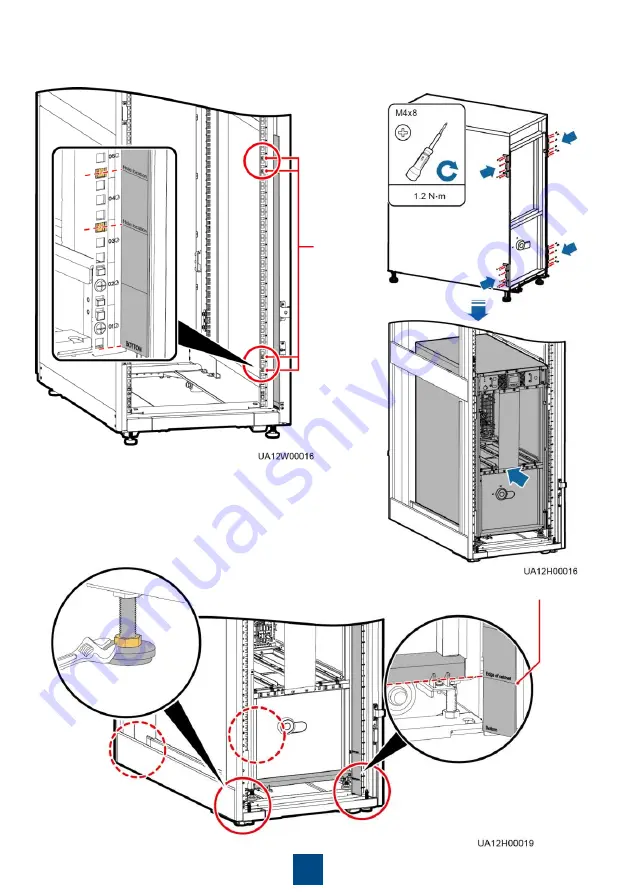
2. Install floating nuts on both sides at the front of 

the rack.

7

Floating 
nuts

3. Remove the front cover and power units.
4. Install mounting ears, and move the 

chassis into the rack.

5. Adjust the anchor bolts until the bottom of the chassis is 

aligned with the scale line on the scale plate, and level the 
UPS.

Edge of cabinet

Summary of Contents for UPS5000-A-120KTTL

Page 1: ...D UPS5000 A 30KTTL UPS5000 A 40KTTL 30 kVA 40 kVA 70 kg 500 mm x 264 mm x 800 mm Tower mounted 264 mm x 500 mm x 800 mm Rack mounted Model Capacity Weight Dimensions H x W x D UPS5000 A 60KTTL UPS5000 A 80KTTL 60 kVA 80 kVA 160 kg 1020 mm x 440 mm x 850 mm UPS5000 A 120KTTL 120 kVA 200 kg The right figure shows the UPS with the front panel and MDU removed Front panel Bypass unit Power unit NOTE MD...

Page 2: ...ions 2 Use insulated tools during installation 3 Only engineers certified by Huawei or its agents are allowed to install commission and maintain the UPS Otherwise personal injury or equipment damage may occur and the UPS faults caused are beyond the warranty scope of Huawei Scenario 1 Tower mounted Installation 1 Assemble support bases 30 kVA 40 kVA UPS 2 1 2 Remove the front panel pull out the re...

Page 3: ... the rear handle back and reinstall the front panel 1 Remove the left and right side panels the handles and the MDU of the UPS 3 Install guide rails in the rack the total height of the guide rails is 2 U and secure the rear end of the guide rails 4 Replace the mounting ears of the power unit Mounting ear in use Original mounting ear ...

Page 4: ...nto the rack and secure it Insert the power and bypass units into the subrack and secure the units by using screws 6 Install the MDU 7 Install the front panel and rotate the Huawei logo on the front panel 90 degrees clockwise ...

Page 5: ...ar Mounting holes for L shaped brackets Front Rear Wall 4 Use the L shaped brackets to secure the cabinet to the floor Scenario 1 Floor Installation 60 kVA 80 kVA 120 kVA UPS 2 2 Secured Installation 2 Adjust the anchor bolts and ensure that the anchor bolts touch the floor Then level the UPS 3 Remove the front and rear covers from the UPS ...

Page 6: ...just the leveling feet Non Secured Installation 1 The rack must comply with IEC297 The rack depth must be greater than or equal to 1100 mm The installation depth of guide rails in the rack must be greater than 820 mm 2 You are advised to install the UPS at the bottom of the rack because the UPS is heavy and requires bottom cabling Scenario 2 Rack Installation 1 Install guide rails on both sides of...

Page 7: ...ack 7 Floating nuts 3 Remove the front cover and power units 4 Install mounting ears and move the chassis into the rack 5 Adjust the anchor bolts until the bottom of the chassis is aligned with the scale line on the scale plate and level the UPS Edge of cabinet ...

Page 8: ...may ignite and cause personal injury or device damage After cables have been installed clean the cabinets in a timely manner Keep the cabinets and surrounding environment clean and tidy You need to prepare terminals onsite The stripped length of the copper wire should be the same as that of the part of the terminal that covers the conductor The cabling route is for reference only Connect cables ba...

Page 9: ...ription Bolt Specifications Torque 1L1 1L2 1L3 N Mains input M6x16 4 N m 2L1 2L2 2L3 N Bypass input M6x16 4 N m N Battery input M8x16 8 N m U V W N Output M6x16 4 N m PE PE M6x16 4 N m Signal cable Battery cable Bypass input power cable not need to be connected when the mains and bypass inputs share a power source Mains input power cable The number and color of signal cables in the preceding figur...

Page 10: ...iddle point between positive and negative battery strings each consisting of 20 batteries NOTE 60 kVA 80 kVA 120 kVA UPS 1 Remove the power distribution unit cover from the rear of the chassis 2 Remove covers from the cabinet bottom based on the number and positions of cables 3 Skip this step if the mains input and bypass input share a power source Remove the copper bars between the mains input an...

Page 11: ...een positive and negative battery strings is the neutral wire Take a battery string consisting of 40 batteries for example The battery neutral wire is routed from the middle point between positive and negative battery strings each consisting of 20 batteries NOTE Silk Screen Port Description Bolt Specifications Torque 1L1 1L2 1L3 N Mains input M10x30 35 N m 2L1 2L2 2L3 N Bypass input M10x30 35 N m ...

Page 12: ...2 After verifying the installation reinstall all the covers 3 Remove the paper protective film from the sealing putty After routing cables and verifying cable connections seal the gap between cables and the cabinet using sealing putty 5 Powering On and Starting the UPS 1 Before powering on the UPS ensure that the UPS has passed all check items in the UPS5000 Commissioning and Acceptance Report and...

Page 13: ... Control menu tap Inv ON On the displayed dialog box choose Startup and press to start the inverter System User LCD Preset Password WebUI Preset Password admin 000001 Changeme operator 000001 Changeme Setting Key Parameters 5 2 1 Set parameters on the Settings Wizard screen During setting the Bypass mode and No battery alarms do not need handling if they are triggered Powering On the UPS 5 1 Close...

Page 14: ...p Inv OFF 2 In the displayed dialog box select Shutdown and press to shut down the inverter 4 Check that the UPS has transferred to normal mode and that the Bypass mode alarm has disappeared Use a multimeter to check that the valid three phase output voltage is 220 V AC 230 V AC or 240 V AC and the frequency is 50 Hz or 60 Hz 5 Close the battery string circuit breaker If there are multiple battery...

Page 15: ... China www huawei com Scan here for more documents You can also log in to Huawei technical support website http support huawei com enterprise http support huawei com Support Support E WeChat Scan here for technical support enterprise Scan here for technical support carrier Huawei App Store Huawei App Store ...

Reviews: