9
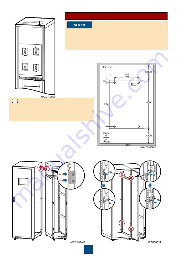
9. Connect signal cables.
The number and color of signal cables in the
figure are for reference only. Signal cables can be
routed along the left or right side of the cabinet.
Route signal cables based on the actual situation.
NOTE
Scenario 2: Routing Cables from the Bottom
A cable entry cabinet needs to be installed when cables are
routed from the bottom. This document uses the cable entry
cabinet installed on the right of the UPS cabinet as an example.
For the cable entry cabinet installed on the left of the UPS
cabinet, refer to the user manual.
1. (Optional) Determine the installation position for the cable
entry cabinet, and draw mounting holes in the installation
position based on drawings.
2. Remove the right and rear covers from the
UPS cabinet, and remove the front and rear
covers from the cable entry cabinet. Put away
the removed screws and covers.
3. Adjust the anchor bolts of the cable entry
cabinet to make it flush with the UPS cabinet.
4. Install equipotential plate mounting kits on the
same horizontal plane of the UPS cabinet and
cable entry cabinet.
5. Place the cable entry cabinet on the right of
the UPS cabinet.
6. Install the front and rear connecting kits.


