UPS5000-A-500 kVA
User Manual (e-shelter)
3 Installation
Issue 02 (2020-01-10)
Copyright © Huawei Technologies Co., Ltd.
41
Procedure
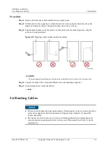
Step 1
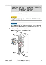
Open the front door of the bypass cabinet and remove the covers of the power distribution
subrack.
The covers of the power distribution subrack can be removed from the bypass cabinet only when all
switches are OFF.
Step 2
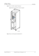
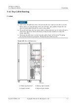
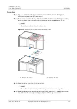
Remove the rear covers from the power cabinet and bypass cabinet.
Step 3
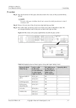
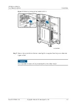
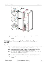
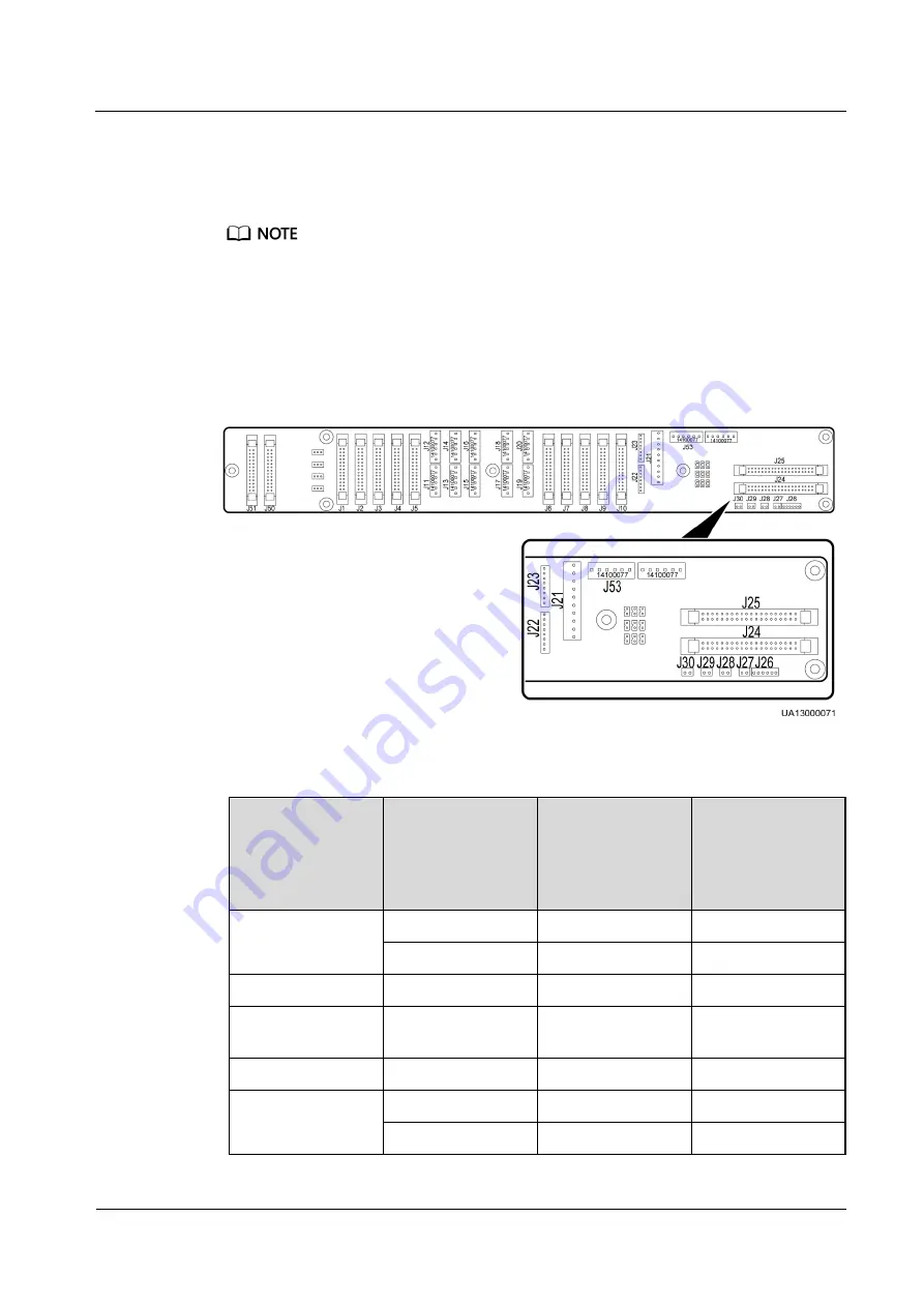
Record the cable connection positions, and remove the cable terminals that connect the
system signal interface board in the power cabinet to the bypass cabinet.
Figure 3-4
Silk screens on the system signal interface board in the power cabinet
Table 3-6
Mapping between cables and ports on the system signal interface board
Bypass Cabinet
Cable Name
Label on the
Cable to be
Connected to the
System Signal
Interface Board
Port Silk Screen
on the System
Signal Interface
Board in the
Power Cabinet
Quantity (PCS)
Bypass unit DL37
cable
W301_J21
J21
1
W303_J24
J24
1
ECM 8-pin cable
W305_J22
J22
1
ECM system
monitoring bus
W307_J25
J25
1
CT cable
W309_J26
J26
1
Switch cable
SW1_J27
J27
1
SW2_J28
J28
1


