UPS5000-S-1200 kVA
User Manual
3 Installation
Issue 04 (2019-06-25)
Copyright © Huawei Technologies Co., Ltd.
48
Put away the removed screws, copper bars and connecting plates to facilitate future cabinet
combination.
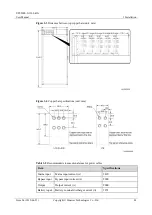
Table 3-5
Specifications and number of screws
Position
Screw Specification
Quantity (PCS)
PE copper bar
M12x35
6
N, L1, L2 and L3 copper
bars
M12x45
40
U, V and W copper bars
M12x45
6
Top epoxy plate
M8x20
3
Bottom epoxy plate
M6x30
4
Top connecting plate
M6x30
4
Middle connecting plate
M6x30
8
Bottom connecting plate
M12x45
8
Procedure
Step 1
Open the front door of the bypass unit and input and output unit.
Step 2
Remove the rear covers from the bypass unit and input and output unit.
Step 3
Remove the PE, N, L1, L2 and L3 copper bars.
Figure 3-6
Remove copper bars
Step 4
Remove cable terminal, U, V and W copper bars and epoxy plate.

