background image

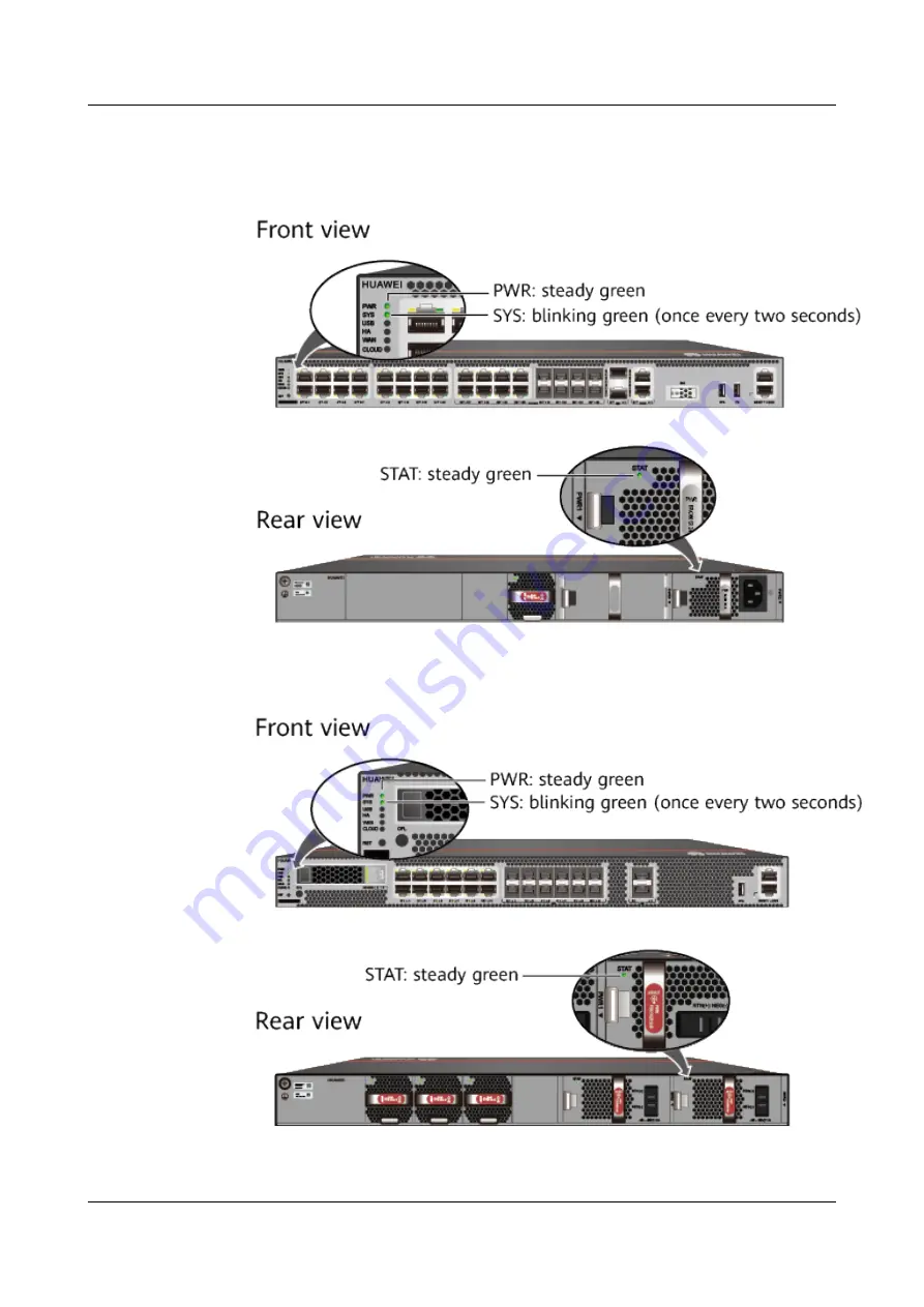
Figure 5-36 Indicators when the USG6515E, USG6525E, USG6550E,

USG6555E, USG6560E, USG6565E, USG6575E-B, USG6580E, USG6585E,

USG6605E-B, USG6610E, USG6615E, USG6620E, USG6625E, USG6630E,

USG6635E, USG6650E, USG6655E (AC model) runs normally


Figure 5-37 Indicators when the USG (DC model) runs normally


HUAWEI USG6000E Series

Hardware Guide

5 Hardware Installation

Issue 08 (2022-04-20)

Copyright © Huawei Technologies Co., Ltd.

560

Summary of Contents for USG6000E Series

Page 1: ...HUAWEI USG6000E Series Hardware Guide Issue 08 Date 2022 04 20 HUAWEI TECHNOLOGIES CO LTD ...

Page 2: ...cribed in this document may not be within the purchase scope or the usage scope Unless otherwise specified in the contract all statements information and recommendations in this document are provided AS IS without warranties guarantees or representations of any kind either express or implied The information in this document is subject to change without notice Every effort has been made in the prep...

Page 3: ...130 4 1 11 USG6580E 146 4 1 12 USG6585E 160 4 1 13 USG6605E B 174 4 1 14 USG6610E 190 4 1 15 USG6615E 204 4 1 16 USG6620E 217 4 1 17 USG6625E 231 4 1 18 USG6630E 244 4 1 19 USG6635E 262 4 1 20 USG6650E 276 4 1 21 USG6655E 290 4 1 22 USG6680E 305 4 1 23 USG6712E 318 4 1 24 USG6716E 331 4 2 Power Modules 345 4 2 1 HW 120300D1D 02220947 36W AC Power Module 345 4 2 2 HW 120300D1D 02221468 36W AC Power...

Page 4: ...torage Devices 413 4 4 1 Hard Disk 413 4 4 1 1 HDD SATA1000G A HardDisk 1000GB SATA 7200rpm 2 5 64M hot swap built in Front Panel Silver 413 4 4 1 2 M 2 SATA240G A M 2 SSD SATA 6Gb s 240GB Hot Swappable 417 4 4 1 3 M 2 SATA64G A M 2 SSD SATA 6Gb s 64GB Hot Swappable 421 4 4 1 4 SSD Sata240G A SSD 240GB SATA 6Gb s Read Intensive 2 5inch 424 4 4 1 5 SSD SATA960G B SSD 960GB SATA 6Gb s Read Intensive...

Page 5: ...61 4 5 6 10 QSFP 40G eSDLC PAM 462 4 5 7 100Gbps QSFP28 Optical Modules 462 4 5 7 1 QSFP 100G CWDM4 463 4 5 7 2 QSFP28 100G LR4 02311KNU 463 4 5 7 3 QSFP28 100G SR4 02311GBW 464 4 5 7 4 QSFP 100G 4WDM 40 465 4 5 7 5 QSFP 100G CWDM4 ISP 466 4 5 7 6 QSFP 100G CWDM4 Lite 467 4 5 7 7 QSFP 100G ER4 467 4 5 7 8 QSFP 100G SWDM4 468 4 5 7 9 QSFP28 100G 1310 40km SM 469 4 5 7 10 QSFP28 100G DR 470 4 5 7 11...

Page 6: ... 5 4 1 Mounting a Device to a Specified Location 534 5 4 1 1 Mounting a Device in a Cabinet 534 5 4 1 2 Mounting a Device on a Workbench 542 5 4 2 Connecting a PGND Cable 544 5 4 3 Installing a Hard Disk 546 5 4 4 Connecting a Console Cable 549 5 4 5 Connecting an Ethernet Cable 551 5 4 6 Installing Optical Transceivers and Connecting Optical Fibers 552 5 4 7 Connecting Power Cables 555 5 4 7 1 Co...

Page 7: ...POE USG6530E 587 6 5 Replacing a Device 589 A Appendix 592 A 1 Requirements for Installation Environment 592 A 1 1 Device Position 592 A 1 2 Humidity Temperature and Cleanness 593 A 1 3 ESD Requirements 594 A 1 4 Lightning Protection and Grounding 596 A 1 5 Power Supply 598 A 1 6 Electromagnetic Protection 601 A 2 Fault Tag 602 HUAWEI USG6000E Series Hardware Guide Contents Issue 08 2022 04 20 Cop...

Page 8: ...Document Related Version The following table lists the product version related to this document HUAWEI USG6000E Series Hardware Guide 1 About This Document Issue 08 2022 04 20 Copyright Huawei Technologies Co Ltd 1 ...

Page 9: ...s hardware structure installation guide and hardware maintenance The content of this document includes the appearance and specifications of the product preparation before the installation installation cabling and hardware replacement This document is intended for installation personnel and administrators who install and maintain USG The installation personnel or administrators must have experience...

Page 10: ...practices not related to personal injury Supplements the important information in the main text NOTE is used to address information not related to personal injury equipment damage and environment deterioration Command Conventions The command conventions that may be found in this document are defined as follows Convention Description Boldface The keywords of a command line are in boldface Italic Co...

Page 11: ...lative Therefore the latest document issue contains all updates made in previous issues Updates in Issue 08 2022 04 20 of Product Version V600R007C20SPC500 The eighth commercial release has the following updates Added the models with the BOM numbers containing 001 USG6525E USG6555E USG6565E USG6585E Added the models with the BOM numbers containing 002 USG6610E USG6620E USG6630E USG6650E Added the ...

Page 12: ...2 5inch Updates in Issue 04 2020 02 27 of Product Version V600R007C00 The fourth commercial release has the following updates Added the PAC60S12 AR 60W AC Power Module Updates in Issue 03 2019 09 25 of Product Version V600R007C00 The third commercial release has the following updates Added the USG6525E USG6555E USG6565E USG6585E Added the USG6615E USG6625E USG6635E AC USG6655E Updates in Issue 02 ...

Page 13: ...for you to produce design drawings and networking diagrams Hardware configuration automatically generates hardware configuration diagrams after you select components are required and calculates the weight power consumption and heat consumption Hardware center provides the technical specifications of devices and components as well as the mapping between devices components and versions 3D model Usin...

Page 14: ...l hardware in this document is supported in this version Before using hardware carefully check the First Supported Version of the hardware in Hardware Guide The Hardware Guide describes all the device models supported in a version and these models may not be available for sales currently To obtain accurate subscription information regularly check the official http e huawei com for product change n...

Page 15: ...Figure 3 1 Software versions compatible with hardware HUAWEI USG6000E Series Hardware Guide 3 Software Versions Compatible with Hardware Issue 08 2022 04 20 Copyright Huawei Technologies Co Ltd 8 ...

Page 16: ...00E For the specific model see the nameplate attached on the bottom of the USG The device series number can be provided using laser marking on the panel or film silkscreen The device functions are the same regardless of the series number presentation mode 4 1 1 USG6510E Overview Table 4 1 Basic information about the USG6510E Description Part Number Model First Supported Version Remarks USG6510E AC...

Page 17: ... 2 GE SFP 1 Adapter 02352PQH 00 1 USG6510E AC V600R007C20 SPC300 Appearance Figure 4 1 Appearance of the USG6510E front view Figure 4 2 Appearance of the USG6510E rear view HUAWEI USG6000E Series Hardware Guide 4 Hardware Overview Issue 08 2022 04 20 Copyright Huawei Technologies Co Ltd 10 ...

Page 18: ...the lower part of the device Protective ground terminal Connects the M4 OT terminal of a PGND cable to the cabinet or the ground bar in the equipment room Fixed interface area Provides clip hole and power receptacle Provides service ports USB ports console ports and out of band management ports for device configuration and maintenance Houses a Micro SD card to store logs and reports MAC label Uniq...

Page 19: ...SD indicators 2 GE electrical port ACT indicator 3 GE electrical port LINK indicator 4 Optical port indicator 5 RST button Table 4 3 Indicators on the USG6510E Silkscreen Name Color Status Description PWR Power indicator Green Steady on The power module works properly Off The power module is faulty or the power cable is disconnected HUAWEI USG6000E Series Hardware Guide 4 Hardware Overview Issue 0...

Page 20: ...y on USB based deployment is complete Green Blink four every second 4 Hz The data of USB based deployment is being read Red Steady on USB based deployment fails Off If USB based deployment is disabled the system is in the default state CLOUD CLOUD indicator Green Steady on Connected to the cloud management platform Green Blink four every second 4 Hz Connecting to the cloud management platform tran...

Page 21: ... through the port Off No data is being sent or received through the port LINK indicator for GE Ethernet electrical ports Green Steady on The link of the port is connected Off The link of the port is disconnected Indicator for optical ports Green Steady on The link of the port is connected Green Blink 12 Hz Data is being sent or received through the port Off The link of the port is disconnected HUA...

Page 22: ...settings with one click To be specific you can hold down the RST button for 5 seconds and then release it to restore the default settings and restart the device Ports Figure 4 5 Ports on the USG6510E 1 Clip hole 2 Power receptacle 3 GE electrical port 4 WAN port 5 GE optical port 6 Micro SD card slot 7 USB 3 0 port 8 Console port HUAWEI USG6000E Series Hardware Guide 4 Hardware Overview Issue 08 2...

Page 23: ... cable clip which is used to bind and fix the power cable Power cable clip Power receptacle The receptacle connects to the tuning fork plug of the power adapter 36 W Power Adapter 02220947 36 W Power Adapter 02221468 HUAWEI USG6000E Series Hardware Guide 4 Hardware Overview Issue 08 2022 04 20 Copyright Huawei Technologies Co Ltd 16 ...

Page 24: ...fault IP address is 192 168 0 1 After this port is connected to your PC through Ethernet cables you can log in to the device using Telnet STelnet or web UI to configure or manage the device NOTE Arrowheads show the positions of ports A down arrowhead indicates a port at the bottom and an up arrowhead indicates a port at the top Ethernet Cable HUAWEI USG6000E Series Hardware Guide 4 Hardware Overvi...

Page 25: ...le Ethernet Cable GE optical port 10 to 11 SFP 2 GE Ethernet optical ports numbered from GigabitEthernet 0 0 10 to GigabitEthernet 0 0 11 Compatible with GE Ethernet optical ports 100Mbps SFP Optical Modules 1Gbps SFP Copper Modules 1Gbps eSFP Optical Modules NOTE In V600R007C20SPC5 00 and later versions GE optical ports support 100Mbps SFP Optical Modules HUAWEI USG6000E Series Hardware Guide 4 H...

Page 26: ...mensions H x W x D 1 mm x 15 00 mm x 11 00 mm 0 04 in x 0 59 in x 0 43 in USB 3 0 port USB 3 0 Type A USB port allows you to insert an USB flash drive for system software upgrades For details on upgrades through USB flash drives refer to the Upgrade Guide delivered with the device NOTE The USB port of the earlier delivered device is USB 2 0 and only USB 2 0 compliant USB flash drives are supported...

Page 27: ...pter 02221468 for power supply Model whose BOM number contains 001 The device has no built in power modules and uses a 36 W Power Adapter 02221468 for power supply Heat Dissipation System The device has no fans and uses natural heat dissipation Technical Specifications Table 4 6 Technical specifications of the USG6510E Item Specification Installation Type Rack Work bench Against the wall Dimension...

Page 28: ...hour Power supply mode Power adapter external Number of power modules 1 Rated input voltage V 100 V to 240 V 50 Hz 60 Hz Input voltage range V 90 V to 264 V 47 Hz to 63 Hz Maximum input current A 1 A Maximum output power W 36 W Types of fans None Number of fan modules 0 Heat dissipation mode Has no fan and uses natural cooling Maximum number of GE ports 2 Maximum number of electrical ports 10 Long...

Page 29: ...mperature and humidity are measured 1 5 m above the floor and 0 4 m in front of the rack when no protection plate exists before or after the rack 4 1 2 USG6510E POE Overview Table 4 7 Basic information about the USG6510E POE Description Part Number Model First Supported Version Remarks USG6510E POE AC Host 10 GE RJ45 2 GE SFP with the AC DC adapter 02352CSC USG6510E POE AC V600R006C00 Appearance F...

Page 30: ...ice running status in real time Protective ground terminal Connects the M4 OT terminal of a PGND cable to the cabinet or the ground bar in the equipment room Fixed interface area Provides clip hole and power receptacle Provides service ports USB ports console ports and out of band management ports for device configuration and maintenance Houses a Micro SD card to store logs and reports HUAWEI USG6...

Page 31: ...d buttons on the USG6510E POE 1 PWR SYS USB CLOUD and MicroSD indicators 2 GE electrical port ACT indicator 3 GE electrical port LINK indicator 4 Optical port indicator 5 RST button Table 4 9 Indicators on the USG6510E POE Silkscreen Name Color Status Description PWR Power indicator Green Steady on The power module works properly Off The power module is faulty or the power cable is disconnected HU...

Page 32: ...y on USB based deployment is complete Green Blink four every second 4 Hz The data of USB based deployment is being read Red Steady on USB based deployment fails Off If USB based deployment is disabled the system is in the default state CLOUD CLOUD indicator Green Steady on Connected to the cloud management platform Green Blink four every second 4 Hz Connecting to the cloud management platform tran...

Page 33: ... through the port Off No data is being sent or received through the port LINK indicator for GE Ethernet electrical ports Green Steady on The link of the port is connected Off The link of the port is disconnected Indicator for optical ports Green Steady on The link of the port is connected Green Blink 12 Hz Data is being sent or received through the port Off The link of the port is disconnected HUA...

Page 34: ...settings with one click To be specific you can hold down the RST button for 5 seconds and then release it to restore the default settings and restart the device Ports Figure 4 10 Ports on the USG6510E POE 1 Clip hole 2 Power receptacle 3 GE electrical port 4 WAN port 5 GE optical port 6 Micro SD card slot 7 USB 3 0 port 8 Console port HUAWEI USG6000E Series Hardware Guide 4 Hardware Overview Issue...

Page 35: ...to install the power cable clip which is used to bind and fix the power cable Power cable clip Power receptacle The receptacle connects to the tuning fork plug of the power adapter 150 W Power Adapter HUAWEI USG6000E Series Hardware Guide 4 Hardware Overview Issue 08 2022 04 20 Copyright Huawei Technologies Co Ltd 28 ...

Page 36: ...port PoE output and can supply power to PDs such as IP phones and surveillance cameras GigabitEthernet 0 0 0 is an inband management port and its default IP address is 192 168 0 1 After this port is connected to your PC through network cables you can log in to the device using Telnet STelnet or web UI to configure or manage the device Ethernet Cable HUAWEI USG6000E Series Hardware Guide 4 Hardware...

Page 37: ...a port at the bottom and an up arrowhead indicates a port at the top WAN ports 8 to 9 RJ45 2 10 100 1000M autosensing Ethernet electrical ports numbered from GigabitEthernet 0 0 8 to GigabitEthernet 0 0 9 The device is connected to the WAN or cloud management platform using a network cable Ethernet Cable HUAWEI USG6000E Series Hardware Guide 4 Hardware Overview Issue 08 2022 04 20 Copyright Huawei...

Page 38: ... to record logs and reports in real time The micro SD card is optional You can purchase one from Huawei if needed You are advised to install an anti theft board delivered with the device to protect the micro SD card SDSDQAE 064G BOM code 06010308 capacity 64GB dimensions H x W x D 1 mm x 15 00 mm x 11 00 mm 0 04 in x 0 59 in x 0 43 in USB 2 0 port USB USB ports allow you to insert USB devices for ...

Page 39: ...pter for power supply Heat Dissipation System The device has no fans and uses natural heat dissipation Technical Specifications Table 4 12 Technical specifications of the USG6510E POE AC Item Specification Installation Type Rack Work bench Against the wall Dimensions without packaging H x W x D mm in 43 6 mm x 250 mm x 210 mm 1 72 in x 9 84 in x 8 27 in Dimensions with packaging H x W x D mm in 11...

Page 40: ...50 Hz 60 Hz Input voltage range V 90 V to 290 V 47 Hz to 63 Hz Maximum input current A 2 A Maximum output power W 150 W Types of fans None Number of fan modules 0 Heat dissipation mode Has no fan and uses natural cooling Maximum number of GE ports 2 Maximum number of electrical ports 10 PoE Supported PoE power interfaces 4 Network cable type and longest transmission IEEE 802 3af 100 m if there is ...

Page 41: ...7 standards Temperature and humidity are measured 1 5 m above the floor and 0 4 m in front of the rack when no protection plate exists before or after the rack 4 1 3 USG6515E Overview Table 4 13 Basic information about the USG6515E Description Part Number Model First Supported Version Remarks USG6515E AC Host 2 GE WAN 8 GE Combo 16 GE RJ45 2 10GE SFP 1 AC power 02352CBP USG6515E AC V600R006C00 App...

Page 42: ... the device in real time and provides the RST button for emergency maintenance Fixed interface area Provides service ports USB ports console ports and out of band management ports for device configuration and maintenance Protective ground terminal Connects the M4 OT terminal of a PGND cable to the cabinet or the ground bar in the equipment room MAC label Uniquely identifies the MAC address of the ...

Page 43: ...n the USG6515E 1 PWR SYS USB HA WAN and CLOUD indicators 2 GE electrical port ACT indicator 3 GE electrical port LINK indicator 4 Optical port ACT indicator 5 Optical port LINK indicator 6 MGMT port indicator 7 RST button NOTE Arrowheads of optical ports show the positions of the ports A down arrowhead indicates a port in the upper part and an up arrowhead indicates a port in the lower part Table ...

Page 44: ... The system is starting Red Steady on A system fault occurs The power module is abnormal The fan module is abnormal NOTE If the system starts with dual power modules but one power module is not powered on the System indicator is steady red but the system is operating properly Off The system is not running USB USB indicator Green Steady on USB based deployment is complete HUAWEI USG6000E Series Har...

Page 45: ...t standby Green Blink every two seconds 0 5 Hz Management backup device in hot standby Red Steady on Hot standby is faulty Off The hot standby function is disabled WAN WAN indicator Off Reserved CLOUD CLOUD indicator Green Steady on Connected to the cloud management platform Green Blink four every second 4 Hz Connecting to the cloud management platform transmitting or receiving data HUAWEI USG6000...

Page 46: ...e link of the port is connected Off The link of the port is disconnected ACT indicator for optical ports Yellow Blink 12 Hz Data is being sent or received through the port Off No data is being sent or received through the port LINK indicator for optical ports Green Steady on The link of the port is connected Off The link of the port is disconnected Indicator for MGMT port Green Steady on The link ...

Page 47: ...ng the RST button This button can enable you to restore the default settings with one click To be specific you can hold down the RST button for 5 seconds and then release it to restore the default settings and restart the device Ports Figure 4 15 Ports on the USG6515E 1 GE electrical port 2 Combo port 3 10GE optical port 4 WAN port 5 SSD card slot 6 USB 3 0 port 7 USB 2 0 port 8 Console port 9 MGM...

Page 48: ...et electrical ports numbered from GigabitEthernet 0 0 0 to GigabitEthernet 0 0 15 NOTE Arrowheads show the positions of ports A down arrowhead indicates a port at the bottom and an up arrowhead indicates a port at the top Ethernet Cable HUAWEI USG6000E Series Hardware Guide 4 Hardware Overview Issue 08 2022 04 20 Copyright Huawei Technologies Co Ltd 41 ...

Page 49: ...cal port is enabled the electrical port is disabled The electrical and optical ports of a combo port use the same interface view numbered from GigabitEthernet 0 0 16 to GigabitEthernet 0 0 23 By default the combo port is used as an electrical port You can use the combo enable copper fiber command to set the working mode of combo ports according to network requirements Ethernet Cable 1Gbps eSFP Opt...

Page 50: ...etwork cable Ethernet Cable SSD card slot The M 2 module is inserted to record logs and reports in real time The M 2 module is optional You can purchase the M 2 module as required Hard Disk Unit M 2 Sata64G A Hard Disk Unit M 2 Sata240G A USB 3 0 port USB 3 0 Type A USB ports allow you to insert USB devices for system software upgrades For details on upgrades through USB devices refer to the Upgra...

Page 51: ... USB flash drive that complies with USB 2 0 Console port RJ45 Console ports allow you to locally connect a PC to the device You can use a console cable to connect the console port RJ45 on the device to the COM port on your PC and use a serial port terminal program on your PC to access configure and manage the device Console Cable HUAWEI USG6000E Series Hardware Guide 4 Hardware Overview Issue 08 2...

Page 52: ... UI to configure manage and maintain the device NOTE The MGMT port cannot be used as a service port Ethernet Cable Power Supply System The power supply system has one PAC60S12 R AC power module but two power modules can be configured for 1 1 power redundancy Heat Dissipation System The heat dissipation system uses one FAN 023A B module to dissipate heat for the system From the front panel the devi...

Page 53: ... packaging H x W x D mm in 43 6 mm x 442 mm x 420 mm 1 72 in x 17 4 in x 16 54 in Dimensions with packaging H x W x D mm in 220 mm x 550 mm x 530 mm 8 66 in x 21 65 in x 20 87 in Chassis height U 1 U Weight with packaging kg lb 8 1 kg lb Weight without packaging kg lb 5 71 kg lb CPU 1 CPU 4 cores CPU up to 1 4 GHz Memory DDR4 4 GB NOR Flash 32 MB HUAWEI USG6000E Series Hardware Guide 4 Hardware Ov...

Page 54: ...cates at the air exhaust of the system Airflow direction Air inlet from front and air outlet from rear Maximum number of 10GE ports 2 Maximum number of GE ports 24 Maximum number of electrical ports 24 Redundant power supply Two power modules are supported for 1 1 power redundancy Long term operating temperature C F 0 C to 45 C Storage temperature C F 40 C to 70 C Long term operating relative humi...

Page 55: ...1 4 USG6525E Overview Table 4 19 Basic information about the USG6525E Description Part Number Model First Supported Version Remarks USG6525E AC Host 2 GE WAN 8 GE Combo 2 10GE SFP 1 AC power 02353AFX USG6525E AC V600R007C00 USG6525E AC Host 2 GE WAN 8 GE Combo 2 10GE SFP 1 AC power 02353AFX 00 1 USG6525E AC V600R007C20 SPC500 Appearance Figure 4 17 Appearance of the USG6525E front view Figure 4 18...

Page 56: ... the device in real time and provides the RST button for emergency maintenance Fixed interface area Provides service ports USB ports console ports and out of band management ports for device configuration and maintenance Protective ground terminal Connects the M4 OT terminal of a PGND cable to the cabinet or the ground bar in the equipment room MAC label Uniquely identifies the MAC address of the ...

Page 57: ...n the USG6525E 1 PWR SYS USB HA WAN and CLOUD indicators 2 GE electrical port ACT indicator 3 GE electrical port LINK indicator 4 Optical port ACT indicator 5 Optical port LINK indicator 6 MGMT port indicator 7 RST button NOTE Arrowheads of optical ports show the positions of the ports A down arrowhead indicates a port in the upper part and an up arrowhead indicates a port in the lower part Table ...

Page 58: ... The system is starting Red Steady on A system fault occurs The power module is abnormal The fan module is abnormal NOTE If the system starts with dual power modules but one power module is not powered on the System indicator is steady red but the system is operating properly Off The system is not running USB USB indicator Green Steady on USB based deployment is complete HUAWEI USG6000E Series Har...

Page 59: ...t standby Green Blink every two seconds 0 5 Hz Management backup device in hot standby Red Steady on Hot standby is faulty Off The hot standby function is disabled WAN WAN indicator Off Reserved CLOUD CLOUD indicator Green Steady on Connected to the cloud management platform Green Blink four every second 4 Hz Connecting to the cloud management platform transmitting or receiving data HUAWEI USG6000...

Page 60: ...e link of the port is connected Off The link of the port is disconnected ACT indicator for optical ports Yellow Blink 12 Hz Data is being sent or received through the port Off No data is being sent or received through the port LINK indicator for optical ports Green Steady on The link of the port is connected Off The link of the port is disconnected Indicator for MGMT port Green Steady on The link ...

Page 61: ...fore pressing the RST button This button can enable you to restore the default settings with one click To be specific you can hold down the RST button for 5 seconds and then release it to restore the default settings and restart the device Ports Figure 4 21 Ports on the USG6525E 1 Combo port 2 10GE optical port 3 WAN port 4 SSD card slot 5 USB 3 0 port 6 USB 2 0 port 7 Console port 8 MGMT port HUA...

Page 62: ...isabled The electrical and optical ports of a combo port use the same interface view numbered from GigabitEthernet 0 0 0 to GigabitEthernet 0 0 7 By default the combo port is used as an electrical port You can use the combo enable copper fiber command to set the working mode of combo ports according to network requirements Ethernet Cable 100Mbps SFP Optical Modules 1Gbps eSFP Optical Modules NOTE ...

Page 63: ... eSFP Optical Modules By default the rate of 10GE optical ports are 10GE You can run the set device port config mode 10ge ge command to set the rate of 10GE optical ports are to 10GE or GE as required 1Gbps SFP Copper Modules 1Gbps eSFP Optical Modules 10Gbps SFP Optical Modules WAN ports 0 to 1 RJ45 2 10 100 1000M autosensing Ethernet electrical ports numbered from WAN 0 0 0 to WAN 0 0 1 The devi...

Page 64: ...are upgrades For details on upgrades through USB devices refer to the Upgrade Guide delivered with the device USB flash drive that complies with USB 2 0 USB flash drive that complies with USB 3 0 USB 2 0 port USB 2 0 Type A USB ports allow you to insert USB devices for system software upgrades For details on upgrades through USB devices refer to the Upgrade Guide delivered with the device USB flas...

Page 65: ...vice You can use a console cable to connect the console port RJ45 on the device to the COM port on your PC and use a serial port terminal program on your PC to access configure and manage the device Console Cable HUAWEI USG6000E Series Hardware Guide 4 Hardware Overview Issue 08 2022 04 20 Copyright Huawei Technologies Co Ltd 58 ...

Page 66: ...gure manage and maintain the device NOTE The MGMT port cannot be used as a service port Ethernet Cable Power Supply System The power supply system has one PAC60S12 AR PAC60S12 R or PAC600S12 CB AC power module Two power modules can be configured for 1 1 power redundancy Heat Dissipation System The heat dissipation system uses one FAN 023A B module to dissipate heat for the system From the front pa...

Page 67: ...in 43 6 mm x 442 mm x 420 mm 1 72 in x 17 4 in x 16 54 in Dimensions with packaging H x W x D mm in 220 mm x 550 mm x 530 mm 8 66 in x 21 65 in x 20 87 in Chassis height U 1 U Weight with packaging kg lb USG6525E AC 02353AFX 8 75 kg lb USG6525E AC 02353AFX 001 7 93 kg lb Weight without packaging kg lb USG6525E AC 02353AFX 5 8 kg lb USG6525E AC 02353AFX 001 5 95 kg lb HUAWEI USG6000E Series Hardwar...

Page 68: ... BTU hour USG6525E AC 02353AFX 136 8 BTU hour USG6525E AC 02353AFX 001 154 4 BTU hour MTBF year 68 98 year MTTR hour 2 hour Power supply mode AC built in Number of power modules 1 Rated input voltage V 100 V to 240 V 50 Hz 60 Hz Input voltage range V 90 V to 290 V 47 Hz to 63 Hz Types of fans Pluggable Number of fan modules 1 Heat dissipation mode The fan module locates at the air exhaust of the s...

Page 69: ...r about 44 45 mm which is a height unit defined in International Electrotechnical Commission IEC 60297 standards Temperature and humidity are measured 1 5 m above the floor and 0 4 m in front of the rack when no protection plate exists before or after the rack 4 1 5 USG6530E Overview Table 4 25 Basic information about the USG6530E Description Part Number Model First Supported Version Remarks USG65...

Page 70: ...he USG6530E rear view Components Figure 4 25 Components of the USG6530E 1 Indicator area 2 Product series ID 3 Protective ground terminal 4 Fixed interface area 5 MAC label HUAWEI USG6000E Series Hardware Guide 4 Hardware Overview Issue 08 2022 04 20 Copyright Huawei Technologies Co Ltd 63 ...

Page 71: ...ovides clip hole and power receptacle Provides service ports USB ports console ports and out of band management ports for device configuration and maintenance Houses a Micro SD card to store logs and reports MAC label Uniquely identifies the MAC address of the device which is required during network forwarding configuration SN label Uniquely identifies the device which needs to be provided for the...

Page 72: ...tem indicator Green Steady on The system is being powered on or restarted Green Blink every two seconds 0 5 Hz The system is running normally Green Blink four every second 4 Hz The system is starting Red Steady on A system fault occurs Off The system is not running USB USB indicator Green Steady on USB based deployment is complete Green Blink four every second 4 Hz The data of USB based deployment...

Page 73: ...to the cloud management platform MicroSD Micro SD indicator Green Steady on The micro SD card is present Off The micro SD card is not detected ACT indicator for GE Ethernet electrical ports Yellow Blink 12 Hz Data is being sent or received through the port Off No data is being sent or received through the port LINK indicator for GE Ethernet electrical ports Green Steady on Data is being sent or re...

Page 74: ...the USG6530E Silkscreen Name Description RST RST button To restart the device press the RST button Ensure that the running configuration is saved before pressing the RST button This button can enable you to restore the default settings with one click To be specific you can hold down the RST button for 5 seconds and then release it to restore the default settings and restart the device HUAWEI USG60...

Page 75: ...r Type Description Available Components Clip hole The hole is used to install the power cable clip which is used to bind and fix the power cable Power cable clip Power receptacle The receptacle connects to the tuning fork plug of the power adapter 36 W Power Adapter 02220947 36 W Power Adapter 02221468 HUAWEI USG6000E Series Hardware Guide 4 Hardware Overview Issue 08 2022 04 20 Copyright Huawei T...

Page 76: ...fault IP address is 192 168 0 1 After this port is connected to your PC through Ethernet cables you can log in to the device using Telnet STelnet or web UI to configure or manage the device NOTE Arrowheads show the positions of ports A down arrowhead indicates a port at the bottom and an up arrowhead indicates a port at the top Ethernet Cable HUAWEI USG6000E Series Hardware Guide 4 Hardware Overvi...

Page 77: ... functions are the same as those of the WAN ports that are horizontally arranged Ethernet Cable 10GE optical ports 0 to 1 SFP 2 GE 10GE autosensing Ethernet optical ports numbered from XGigabitEthernet 0 0 0 to XGigabitEthernet 0 0 1 100Mbps SFP Optical Modules 1Gbps SFP Copper Modules 1Gbps eSFP Optical Modules 10Gbps SFP Optical Modules NOTE In V600R007C20SPC5 00 and later versions 10GE optical ...

Page 78: ...mensions H x W x D 1 mm x 15 00 mm x 11 00 mm 0 04 in x 0 59 in x 0 43 in USB 3 0 port USB 3 0 Type A USB port allows you to insert an USB flash drive for system software upgrades For details on upgrades through USB flash drives refer to the Upgrade Guide delivered with the device NOTE The USB port of the earlier delivered device is USB 2 0 and only USB 2 0 compliant USB flash drives are supported...

Page 79: ...pter 02221468 for power supply Model whose BOM number contains 001 The device has no built in power modules and uses a 36 W Power Adapter 02221468 for power supply Heat Dissipation System The device has no fans and uses natural heat dissipation Technical Specifications Table 4 30 Technical specifications of the USG6530E Item Specification Installation Type Rack Work bench Against the wall Dimensio...

Page 80: ...29 year MTTR hour 2 hour Power supply mode Power adapter external Number of power modules 1 Rated input voltage V 100 V to 240 V 50 Hz 60 Hz Input voltage range V 90 V to 264 V 47 Hz to 63 Hz Maximum input current A 1 A Maximum output power W 36 W Types of fans None Number of fan modules 0 Heat dissipation mode Has no fan and uses natural cooling Maximum number of 10GE ports 2 Maximum number of GE...

Page 81: ...7 standards Temperature and humidity are measured 1 5 m above the floor and 0 4 m in front of the rack when no protection plate exists before or after the rack 4 1 6 USG6550E Overview Table 4 31 Basic information about the USG6550E Description Part Number Model First Supported Version Remarks USG6550E AC Host 2 GE WAN 8 GE Combo 16 GE RJ45 2 10GE SFP 1 AC power 02352CBQ USG6550E AC V600R006C00 App...

Page 82: ... the device in real time and provides the RST button for emergency maintenance Fixed interface area Provides service ports USB ports console ports and out of band management ports for device configuration and maintenance Protective ground terminal Connects the M4 OT terminal of a PGND cable to the cabinet or the ground bar in the equipment room MAC label Uniquely identifies the MAC address of the ...

Page 83: ...n the USG6550E 1 PWR SYS USB HA WAN and CLOUD indicators 2 GE electrical port ACT indicator 3 GE electrical port LINK indicator 4 Optical port ACT indicator 5 Optical port LINK indicator 6 MGMT port indicator 7 RST button NOTE Arrowheads of optical ports show the positions of the ports A down arrowhead indicates a port in the upper part and an up arrowhead indicates a port in the lower part Table ...

Page 84: ... The system is starting Red Steady on A system fault occurs The power module is abnormal The fan module is abnormal NOTE If the system starts with dual power modules but one power module is not powered on the System indicator is steady red but the system is operating properly Off The system is not running USB USB indicator Green Steady on USB based deployment is complete HUAWEI USG6000E Series Har...

Page 85: ...t standby Green Blink every two seconds 0 5 Hz Management backup device in hot standby Red Steady on Hot standby is faulty Off The hot standby function is disabled WAN WAN indicator Off Reserved CLOUD CLOUD indicator Green Steady on Connected to the cloud management platform Green Blink four every second 4 Hz Connecting to the cloud management platform transmitting or receiving data HUAWEI USG6000...

Page 86: ...e link of the port is connected Off The link of the port is disconnected ACT indicator for optical ports Yellow Blink 12 Hz Data is being sent or received through the port Off No data is being sent or received through the port LINK indicator for optical ports Green Steady on The link of the port is connected Off The link of the port is disconnected Indicator for MGMT port Green Steady on The link ...

Page 87: ...ng the RST button This button can enable you to restore the default settings with one click To be specific you can hold down the RST button for 5 seconds and then release it to restore the default settings and restart the device Ports Figure 4 32 Ports on the USG6550E 1 GE electrical port 2 Combo port 3 10GE optical port 4 WAN port 5 SSD card slot 6 USB 3 0 port 7 USB 2 0 port 8 Console port 9 MGM...

Page 88: ...et electrical ports numbered from GigabitEthernet 0 0 0 to GigabitEthernet 0 0 15 NOTE Arrowheads show the positions of ports A down arrowhead indicates a port at the bottom and an up arrowhead indicates a port at the top Ethernet Cable HUAWEI USG6000E Series Hardware Guide 4 Hardware Overview Issue 08 2022 04 20 Copyright Huawei Technologies Co Ltd 81 ...

Page 89: ...cal port is enabled the electrical port is disabled The electrical and optical ports of a combo port use the same interface view numbered from GigabitEthernet 0 0 16 to GigabitEthernet 0 0 23 By default the combo port is used as an electrical port You can use the combo enable copper fiber command to set the working mode of combo ports according to network requirements Ethernet Cable 1Gbps eSFP Opt...

Page 90: ...enter using a network cable Ethernet Cable SSD card slot The M 2 module is inserted to record logs and reports in real time The M 2 module is optional You can purchase the M 2 module as required Hard Disk Unit M 2 Sata240G A USB 3 0 port USB 3 0 Type A USB ports allow you to insert USB devices for system software upgrades For details on upgrades through USB devices refer to the Upgrade Guide deliv...

Page 91: ... USB flash drive that complies with USB 2 0 Console port RJ45 Console ports allow you to locally connect a PC to the device You can use a console cable to connect the console port RJ45 on the device to the COM port on your PC and use a serial port terminal program on your PC to access configure and manage the device Console Cable HUAWEI USG6000E Series Hardware Guide 4 Hardware Overview Issue 08 2...

Page 92: ... UI to configure manage and maintain the device NOTE The MGMT port cannot be used as a service port Ethernet Cable Power Supply System The power supply system has one PAC60S12 R AC power module but two power modules can be configured for 1 1 power redundancy Heat Dissipation System The heat dissipation system uses one FAN 023A B module to dissipate heat for the system From the front panel the devi...

Page 93: ... packaging H x W x D mm in 43 6 mm x 442 mm x 420 mm 1 72 in x 17 4 in x 16 54 in Dimensions with packaging H x W x D mm in 220 mm x 550 mm x 530 mm 8 66 in x 21 65 in x 20 87 in Chassis height U 1 U Weight with packaging kg lb 8 1 kg lb Weight without packaging kg lb 5 71 kg lb CPU 1 CPU 4 cores CPU up to 1 4 GHz Memory DDR4 4 GB NOR Flash 32 MB HUAWEI USG6000E Series Hardware Guide 4 Hardware Ov...

Page 94: ...tes at the air exhaust of the system Airflow direction Air inlet from front and air outlet from rear Maximum number of 10GE ports 2 Maximum number of GE ports 24 Maximum number of electrical ports 24 Redundant power supply Two power modules are supported for 1 1 power redundancy Long term operating temperature C F 0 C to 45 C Storage temperature C F 40 C to 70 C Long term operating relative humidi...

Page 95: ...1 7 USG6555E Overview Table 4 37 Basic information about the USG6555E Description Part Number Model First Supported Version Remarks USG6555E AC Host 2 GE WAN 8 GE Combo 2 10GE SFP 1 AC power 02353AEK USG6555E AC V600R007C00 USG6555E AC Host 2 GE WAN 8 GE Combo 2 10GE SFP 1 AC power 02353AEK 00 1 USG6555E AC V600R007C20 SPC500 Appearance Figure 4 34 Appearance of the USG6555E front view Figure 4 35...

Page 96: ... the device in real time and provides the RST button for emergency maintenance Fixed interface area Provides service ports USB ports console ports and out of band management ports for device configuration and maintenance Protective ground terminal Connects the M4 OT terminal of a PGND cable to the cabinet or the ground bar in the equipment room MAC label Uniquely identifies the MAC address of the ...

Page 97: ...n the USG6555E 1 PWR SYS USB HA WAN and CLOUD indicators 2 GE electrical port ACT indicator 3 GE electrical port LINK indicator 4 Optical port ACT indicator 5 Optical port LINK indicator 6 MGMT port indicator 7 RST button NOTE Arrowheads of optical ports show the positions of the ports A down arrowhead indicates a port in the upper part and an up arrowhead indicates a port in the lower part Table ...

Page 98: ... The system is starting Red Steady on A system fault occurs The power module is abnormal The fan module is abnormal NOTE If the system starts with dual power modules but one power module is not powered on the System indicator is steady red but the system is operating properly Off The system is not running USB USB indicator Green Steady on USB based deployment is complete HUAWEI USG6000E Series Har...

Page 99: ...t standby Green Blink every two seconds 0 5 Hz Management backup device in hot standby Red Steady on Hot standby is faulty Off The hot standby function is disabled WAN WAN indicator Off Reserved CLOUD CLOUD indicator Green Steady on Connected to the cloud management platform Green Blink four every second 4 Hz Connecting to the cloud management platform transmitting or receiving data HUAWEI USG6000...

Page 100: ...e link of the port is connected Off The link of the port is disconnected ACT indicator for optical ports Yellow Blink 12 Hz Data is being sent or received through the port Off No data is being sent or received through the port LINK indicator for optical ports Green Steady on The link of the port is connected Off The link of the port is disconnected Indicator for MGMT port Green Steady on The link ...

Page 101: ...fore pressing the RST button This button can enable you to restore the default settings with one click To be specific you can hold down the RST button for 5 seconds and then release it to restore the default settings and restart the device Ports Figure 4 38 Ports on the USG6555E 1 Combo port 2 10GE optical port 3 WAN port 4 SSD card slot 5 USB 3 0 port 6 USB 2 0 port 7 Console port 8 MGMT port HUA...

Page 102: ...isabled The electrical and optical ports of a combo port use the same interface view numbered from GigabitEthernet 0 0 0 to GigabitEthernet 0 0 7 By default the combo port is used as an electrical port You can use the combo enable copper fiber command to set the working mode of combo ports according to network requirements Ethernet Cable 100Mbps SFP Optical Modules 1Gbps eSFP Optical Modules NOTE ...

Page 103: ... eSFP Optical Modules By default the rate of 10GE optical ports are 10GE You can run the set device port config mode 10ge ge command to set the rate of 10GE optical ports are to 10GE or GE as required 1Gbps SFP Copper Modules 1Gbps eSFP Optical Modules 10Gbps SFP Optical Modules WAN ports 0 to 1 RJ45 2 10 100 1000M autosensing Ethernet electrical ports numbered from WAN 0 0 0 to WAN 0 0 1 The devi...

Page 104: ...r details on upgrades through USB devices refer to the Upgrade Guide delivered with the device USB flash drive that complies with USB 2 0 USB flash drive that complies with USB 3 0 USB 2 0 port USB 2 0 Type A USB ports allow you to insert USB devices for system software upgrades For details on upgrades through USB devices refer to the Upgrade Guide delivered with the device USB flash drive that co...

Page 105: ...vice You can use a console cable to connect the console port RJ45 on the device to the COM port on your PC and use a serial port terminal program on your PC to access configure and manage the device Console Cable HUAWEI USG6000E Series Hardware Guide 4 Hardware Overview Issue 08 2022 04 20 Copyright Huawei Technologies Co Ltd 98 ...

Page 106: ...gure manage and maintain the device NOTE The MGMT port cannot be used as a service port Ethernet Cable Power Supply System The power supply system has one PAC60S12 AR PAC60S12 R or PAC600S12 CB AC power module Two power modules can be configured for 1 1 power redundancy Heat Dissipation System The heat dissipation system uses one FAN 023A B module to dissipate heat for the system From the front pa...

Page 107: ...in 43 6 mm x 442 mm x 420 mm 1 72 in x 17 4 in x 16 54 in Dimensions with packaging H x W x D mm in 220 mm x 550 mm x 530 mm 8 66 in x 21 65 in x 20 87 in Chassis height U 1 U Weight with packaging kg lb USG6555E AC 02353AEK 8 75 kg lb USG6555E AC 02353AEK 001 7 93 kg lb Weight without packaging kg lb USG6555E AC 02353AEK 5 8 kg lb USG6555E AC 02353AEK 001 5 95 kg lb HUAWEI USG6000E Series Hardwar...

Page 108: ...U hour USG6555E AC 02353AEK 136 8 BTU hour USG6555E AC 02353AEK 001 154 4 BTU hour MTBF year 68 98 year MTTR hour 2 hour Power supply mode AC built in Number of power modules 1 Rated input voltage V 100 V to 240 V 50 Hz 60 Hz Input voltage range V 90 V to 290 V 47 Hz to 63 Hz Types of fans Pluggable Number of fan modules 1 Heat dissipation mode The fan module locates at the air exhaust of the syst...

Page 109: ...ches or about 44 45 mm which is a height unit defined in International Electrotechnical Commission IEC 60297 standards Temperature and humidity are measured 1 5 m above the floor and 0 4 m in front of the rack when no protection plate exists before or after the rack 4 1 8 USG6560E Overview Table 4 43 Basic information about the USG6560E Description Part Number Model First Supported Version Remarks...

Page 110: ...oduct model see the nameplate in the lower part of the device Indicator and button area Provides multiple indicators to display the running status of the device in real time and provides the RST button for emergency maintenance Fixed interface area Provides service ports USB ports console ports and out of band management ports for device configuration and maintenance Protective ground terminal Con...

Page 111: ...o power modules can be configured to achieve 1 1 power redundancy When one power module is running properly the other one is hot swappable Indicators and Buttons Figure 4 43 Indicators and buttons on the USG6560E 1 PWR SYS USB HA WAN and CLOUD indicators 2 GE electrical port ACT indicator 3 GE electrical port LINK indicator 4 Optical port ACT indicator 5 Optical port LINK indicator 6 MGMT port ind...

Page 112: ...y two seconds 0 5 Hz The system is running normally Green Blink four every second 4 Hz The system is starting Red Steady on A system fault occurs The power module is abnormal The fan module is abnormal NOTE If the system starts with dual power modules but one power module is not powered on the System indicator is steady red but the system is operating properly Off The system is not running HUAWEI ...

Page 113: ...on Management master device in hot standby Green Blink every two seconds 0 5 Hz Management backup device in hot standby Red Steady on Hot standby is faulty Off The hot standby function is disabled WAN WAN indicator Off Reserved CLOUD CLOUD indicator Green Steady on Connected to the cloud management platform Green Blink four every second 4 Hz Connecting to the cloud management platform transmitting...

Page 114: ...e link of the port is connected Off The link of the port is disconnected ACT indicator for optical ports Yellow Blink 12 Hz Data is being sent or received through the port Off No data is being sent or received through the port LINK indicator for optical ports Green Steady on The link of the port is connected Off The link of the port is disconnected Indicator for MGMT port Green Steady on The link ...

Page 115: ...ng the RST button This button can enable you to restore the default settings with one click To be specific you can hold down the RST button for 5 seconds and then release it to restore the default settings and restart the device Ports Figure 4 44 Ports on the USG6560E 1 GE electrical port 2 Combo port 3 10GE optical port 4 WAN port 5 SSD card slot 6 USB 3 0 port 7 USB 2 0 port 8 Console port 9 MGM...

Page 116: ...et electrical ports numbered from GigabitEthernet 0 0 0 to GigabitEthernet 0 0 15 NOTE Arrowheads show the positions of ports A down arrowhead indicates a port at the bottom and an up arrowhead indicates a port at the top Ethernet Cable HUAWEI USG6000E Series Hardware Guide 4 Hardware Overview Issue 08 2022 04 20 Copyright Huawei Technologies Co Ltd 109 ...

Page 117: ...cal port is enabled the electrical port is disabled The electrical and optical ports of a combo port use the same interface view numbered from GigabitEthernet 0 0 16 to GigabitEthernet 0 0 23 By default the combo port is used as an electrical port You can use the combo enable copper fiber command to set the working mode of combo ports according to network requirements Ethernet Cable 1Gbps eSFP Opt...

Page 118: ...nter using a network cable Ethernet Cable SSD card slot The M 2 module is inserted to record logs and reports in real time The M 2 module is optional You can purchase the M 2 module as required Hard Disk Unit M 2 Sata240G A USB 3 0 port USB 3 0 Type A USB ports allow you to insert USB devices for system software upgrades For details on upgrades through USB devices refer to the Upgrade Guide delive...

Page 119: ... USB flash drive that complies with USB 2 0 Console port RJ45 Console ports allow you to locally connect a PC to the device You can use a console cable to connect the console port RJ45 on the device to the COM port on your PC and use a serial port terminal program on your PC to access configure and manage the device Console Cable HUAWEI USG6000E Series Hardware Guide 4 Hardware Overview Issue 08 2...

Page 120: ... UI to configure manage and maintain the device NOTE The MGMT port cannot be used as a service port Ethernet Cable Power Supply System The power supply system has one PAC60S12 R AC power module but two power modules can be configured for 1 1 power redundancy Heat Dissipation System The heat dissipation system uses one FAN 023A B module to dissipate heat for the system From the front panel the devi...

Page 121: ... packaging H x W x D mm in 43 6 mm x 442 mm x 420 mm 1 72 in x 17 4 in x 16 54 in Dimensions with packaging H x W x D mm in 220 mm x 550 mm x 530 mm 8 66 in x 21 65 in x 20 87 in Chassis height U 1 U Weight with packaging kg lb 8 1 kg lb Weight without packaging kg lb 5 71 kg lb CPU 1 CPU 4 cores CPU up to 1 4 GHz Memory DDR4 4 GB NOR Flash 32 MB HUAWEI USG6000E Series Hardware Guide 4 Hardware Ov...

Page 122: ...es at the air exhaust of the system Airflow direction Air inlet from front and air outlet from rear Maximum number of 10GE ports 2 Maximum number of GE ports 24 Maximum number of electrical ports 24 Redundant power supply Two power modules are supported for 1 1 power redundancy Long term operating temperature C F 0 C to 45 C Storage temperature C F 40 C to 70 C Long term operating relative humidit...

Page 123: ...1 9 USG6565E Overview Table 4 49 Basic information about the USG6565E Description Part Number Model First Supported Version Remarks USG6565E AC Host 2 GE WAN 8 GE Combo 2 10GE SFP 1 AC power 02353AEJ USG6565E AC V600R007C00 USG6565E AC Host 2 GE WAN 8 GE Combo 2 10GE SFP 1 AC power 02353AEJ 001 USG6565E AC V600R007C20 SPC500 Appearance Figure 4 46 Appearance of the USG6565E front view Figure 4 47 ...

Page 124: ...the device in real time and provides the RST button for emergency maintenance Fixed interface area Provides service ports USB ports console ports and out of band management ports for device configuration and maintenance Protective ground terminal Connects the M4 OT terminal of a PGND cable to the cabinet or the ground bar in the equipment room MAC label Uniquely identifies the MAC address of the d...

Page 125: ...n the USG6565E 1 PWR SYS USB HA WAN and CLOUD indicators 2 GE electrical port ACT indicator 3 GE electrical port LINK indicator 4 Optical port ACT indicator 5 Optical port LINK indicator 6 MGMT port indicator 7 RST button NOTE Arrowheads of optical ports show the positions of the ports A down arrowhead indicates a port in the upper part and an up arrowhead indicates a port in the lower part Table ...

Page 126: ... The system is starting Red Steady on A system fault occurs The power module is abnormal The fan module is abnormal NOTE If the system starts with dual power modules but one power module is not powered on the System indicator is steady red but the system is operating properly Off The system is not running USB USB indicator Green Steady on USB based deployment is complete HUAWEI USG6000E Series Har...

Page 127: ... standby Green Blink every two seconds 0 5 Hz Management backup device in hot standby Red Steady on Hot standby is faulty Off The hot standby function is disabled WAN WAN indicator Off Reserved CLOUD CLOUD indicator Green Steady on Connected to the cloud management platform Green Blink four every second 4 Hz Connecting to the cloud management platform transmitting or receiving data HUAWEI USG6000E...

Page 128: ...e link of the port is connected Off The link of the port is disconnected ACT indicator for optical ports Yellow Blink 12 Hz Data is being sent or received through the port Off No data is being sent or received through the port LINK indicator for optical ports Green Steady on The link of the port is connected Off The link of the port is disconnected Indicator for MGMT port Green Steady on The link ...

Page 129: ...ore pressing the RST button This button can enable you to restore the default settings with one click To be specific you can hold down the RST button for 5 seconds and then release it to restore the default settings and restart the device Ports Figure 4 50 Ports on the USG6565E 1 Combo port 2 10GE optical port 3 WAN port 4 SSD card slot 5 USB 3 0 port 6 USB 2 0 port 7 Console port 8 MGMT port HUAW...

Page 130: ...sabled The electrical and optical ports of a combo port use the same interface view numbered from GigabitEthernet 0 0 0 to GigabitEthernet 0 0 7 By default the combo port is used as an electrical port You can use the combo enable copper fiber command to set the working mode of combo ports according to network requirements Ethernet Cable 100Mbps SFP Optical Modules 1Gbps eSFP Optical Modules NOTE I...

Page 131: ... eSFP Optical Modules By default the rate of 10GE optical ports are 10GE You can run the set device port config mode 10ge ge command to set the rate of 10GE optical ports are to 10GE or GE as required 1Gbps SFP Copper Modules 1Gbps eSFP Optical Modules 10Gbps SFP Optical Modules WAN ports 0 to 1 RJ45 2 10 100 1000M autosensing Ethernet electrical ports numbered from WAN 0 0 0 to WAN 0 0 1 The devi...

Page 132: ...r details on upgrades through USB devices refer to the Upgrade Guide delivered with the device USB flash drive that complies with USB 2 0 USB flash drive that complies with USB 3 0 USB 2 0 port USB 2 0 Type A USB ports allow you to insert USB devices for system software upgrades For details on upgrades through USB devices refer to the Upgrade Guide delivered with the device USB flash drive that co...

Page 133: ...ice You can use a console cable to connect the console port RJ45 on the device to the COM port on your PC and use a serial port terminal program on your PC to access configure and manage the device Console Cable HUAWEI USG6000E Series Hardware Guide 4 Hardware Overview Issue 08 2022 04 20 Copyright Huawei Technologies Co Ltd 126 ...

Page 134: ...gure manage and maintain the device NOTE The MGMT port cannot be used as a service port Ethernet Cable Power Supply System The power supply system has one PAC60S12 AR PAC60S12 R or PAC600S12 CB AC power module Two power modules can be configured for 1 1 power redundancy Heat Dissipation System The heat dissipation system uses one FAN 023A B module to dissipate heat for the system From the front pa...

Page 135: ...in 43 6 mm x 442 mm x 420 mm 1 72 in x 17 4 in x 16 54 in Dimensions with packaging H x W x D mm in 220 mm x 550 mm x 530 mm 8 66 in x 21 65 in x 20 87 in Chassis height U 1 U Weight with packaging kg lb USG6565E AC 02353AEJ 8 75 kg lb USG6565E AC 02353AEJ 001 7 93 kg lb Weight without packaging kg lb USG6565E AC 02353AEJ 5 8 kg lb USG6565E AC 02353AEJ 001 5 95 kg lb HUAWEI USG6000E Series Hardwar...

Page 136: ...U hour USG6565E AC 02353AEJ 136 8 BTU hour USG6565E AC 02353AEJ 001 154 4 BTU hour MTBF year 68 98 year MTTR hour 2 hour Power supply mode AC built in Number of power modules 1 Rated input voltage V 100 V to 240 V 50 Hz 60 Hz Input voltage range V 90 V to 290 V 47 Hz to 63 Hz Types of fans Pluggable Number of fan modules 1 Heat dissipation mode The fan module locates at the air exhaust of the syst...

Page 137: ...rs The height is 1U 1U 1 75 inches or about 44 45 mm which is a height unit defined in International Electrotechnical Commission IEC 60297 standards Temperature and humidity are measured 1 5 m above the floor and 0 4 m in front of the rack when no protection plate exists before or after the rack 4 1 10 USG6575E B Overview Table 4 55 Basic information about the USG6575E B Description Part Number Mo...

Page 138: ...mponents of the USG6575E B 1 Product series ID 2 Indicator and button area 3 HDD SSD slot 4 Fixed interface area 5 Protective ground terminal 6 MAC label 7 SN label 8 Fan module 9 Optional power module slot 10 Power module HUAWEI USG6000E Series Hardware Guide 4 Hardware Overview Issue 08 2022 04 20 Copyright Huawei Technologies Co Ltd 131 ...

Page 139: ... ground bar in the equipment room MAC label Uniquely identifies the MAC address of the device which is required during network forwarding configuration SN label Uniquely identifies the device which needs to be provided for the local technical support personnel to apply for a license Fan module Dissipates heat for the device and is swappable The fan module can be removed for no more than 1 minute P...

Page 140: ...pper part and an up arrowhead indicates a port in the lower part Table 4 57 Indicators on the USG6575E B Silkscreen Name Color Status Description PWR Power indicator Green Steady on The power module works properly Off The power module is faulty or the power cable is disconnected SYS System indicator Green Steady on The system is being powered on or restarted Green Blink every two seconds 0 5 Hz Th...

Page 141: ...erly Off The system is not running USB USB indicator Green Steady on USB based deployment is complete Green Blink four every second 4 Hz The data of USB based deployment is being read Red Steady on USB based deployment fails Off If USB based deployment is disabled the system is in the default state HA HA indicator Green Steady on Management master device in hot standby HUAWEI USG6000E Series Hardw...

Page 142: ...Connected to the cloud management platform Green Blink four every second 4 Hz Connecting to the cloud management platform transmitting or receiving data Off Not connected or registered to the cloud management platform BLE Bluetooth indicator Off Reserved OFL indicator Green Steady on The hard disk is removable Off The hard disk cannot be removed HUAWEI USG6000E Series Hardware Guide 4 Hardware Ove...

Page 143: ...e Off Device is powered off The bypass formed by GigabitEthern et0 0 20 and GigabitEthern et0 0 21 is in protection state Bypass Bypass indicator 1 Green Steady on Device is powered on The bypass formed by GigabitEthern et0 0 22 and GigabitEthern et0 0 23 is in protection state Green Blink every two seconds 0 5 Hz Device is powered on The bypass formed by GigabitEthern et0 0 22 and GigabitEthern e...

Page 144: ...NK indicator for GE Ethernet electrical ports Green Steady on The link of the port is connected Off The link of the port is disconnected ACT indicator for optical ports Yellow Blink 12 Hz Data is being sent or received through the port Off No data is being sent or received through the port LINK indicator for optical ports Green Steady on The link of the port is connected Off The link of the port i...

Page 145: ...he running configuration is saved before pressing the RST button This button can enable you to restore the default settings with one click To be specific you can hold down the RST button for 5 seconds and then release it to restore the default settings and restart the device OFL OFL button To remove a hard disk press and hold the OFL button for four seconds until the OFL indicator turns on Ports F...

Page 146: ...isk Unit SSD Sata240G A Hard Disk Unit SSD SATA960G B Hard Disk Unit HDD SATA1000G A GE electrical ports 0 to 15 RJ45 16 10 100 1000M autosensing Ethernet electrical ports numbered from GigabitEthernet 0 0 0 to GigabitEthernet 0 0 15 NOTE Arrowheads show the positions of ports A down arrowhead indicates a port at the bottom and an up arrowhead indicates a port at the top Ethernet Cable HUAWEI USG6...

Page 147: ...w numbered from GigabitEthernet 0 0 16 to GigabitEthernet 0 0 23 Among the four GE ports from GigabitEthernet0 0 20 to GigabitEthernet0 0 23 GigabitEthernet0 0 20 and GigabitEthernet0 0 21 are a pair of two bypass interfaces and GigabitEthernet0 0 22 and GigabitEthernet0 0 23 are another pair When the interfaces of each bypass interface pair work at Layer Ethernet Cable 100Mbps SFP Optical Modules...

Page 148: ...e of combo ports according to network requirements NOTE A bypass link can be established only when GigabitEthernet0 0 20 to GigabitEthernet0 0 23 work as electrical ports Arrowheads show the positions of ports A down arrowhead indicates a port at the bottom and an up arrowhead indicates a port at the top HUAWEI USG6000E Series Hardware Guide 4 Hardware Overview Issue 08 2022 04 20 Copyright Huawei...

Page 149: ...ou to insert USB devices for system software upgrades For details on upgrades through USB devices refer to the Upgrade Guide delivered with the device USB flash drive that complies with USB 2 0 USB flash drive that complies with USB 3 0 Console port RJ45 Console ports allow you to locally connect a PC to the device You can use a console cable to connect the console port RJ45 on the device to the C...

Page 150: ...I to configure manage and maintain the device NOTE The MGMT port cannot be used as a service port Ethernet Cable Power Supply System The power supply system has one PAC150S12 R AC power module but two power modules can be configured for 1 1 power redundancy Heat Dissipation System The heat dissipation system consists of two FAN 023A B modules working in 1 1 backup mode From the front panel the dev...

Page 151: ...ing H x W x D mm in 43 6 mm x 442 mm x 420 mm 1 72 in x 17 4 in x 16 54 in Dimensions with packaging H x W x D mm in 175 mm x 650 mm x 550 mm 6 89 in x 25 59 in x 21 65 in Chassis height U 1 U Weight with packaging kg lb 8 25 kg lb Weight without packaging kg lb 6 25 kg lb CPU 1 CPU 4 cores CPU up to 1 4 GHz Memory DDR4 8 GB NOR Flash 64 MB NAND Flash 2 GB HUAWEI USG6000E Series Hardware Guide 4 H...

Page 152: ... V to 264 V 47 Hz to 63 Hz Maximum input current A 3 A Rated output power W 150W 12V Maximum output power W 150 W Types of fans Pluggable Number of fan modules 2 Heat dissipation mode The fan module locates at the air exhaust of the system Airflow direction Air inlet from front and air outlet from rear Maximum number of 10GE ports 2 Maximum number of GE ports 8 Maximum number of electrical ports 2...

Page 153: ...ches or about 44 45 mm which is a height unit defined in International Electrotechnical Commission IEC 60297 standards Temperature and humidity are measured 1 5 m above the floor and 0 4 m in front of the rack when no protection plate exists before or after the rack The operating temperature change rate of a device with HDDs must be less than or equal to 20 C hour 4 1 11 USG6580E Overview Table 4 ...

Page 154: ...wer module slot 9 Power module Table 4 62 Component functions Name Description Product series ID Indicates the product series of the device For details about the product model see the nameplate in the lower part of the device Indicator and button area Provides multiple indicators to display the running status of the device in real time and provides the RST button for emergency maintenance HUAWEI U...

Page 155: ...heat for the device and is swappable The fan module can be removed for no more than 1 minute Power module Provides power input and distribution for the device One power module is included in the standard configuration Two power modules can be configured to achieve 1 1 power redundancy When one power module is running properly the other one is hot swappable Indicators and Buttons Figure 4 61 Indica...

Page 156: ...ted SYS System indicator Green Steady on The system is being powered on or restarted Green Blink every two seconds 0 5 Hz The system is running normally Green Blink four every second 4 Hz The system is starting Red Steady on A system fault occurs The power module is abnormal The fan module is abnormal NOTE If the system starts with dual power modules but one power module is not powered on the Syst...

Page 157: ...abled the system is in the default state HA HA indicator Green Steady on Management master device in hot standby Green Blink every two seconds 0 5 Hz Management backup device in hot standby Red Steady on Hot standby is faulty Off The hot standby function is disabled WAN WAN indicator Off Reserved CLOUD CLOUD indicator Green Steady on Connected to the cloud management platform HUAWEI USG6000E Serie...

Page 158: ...ta is being sent or received through the port LINK indicator for GE Ethernet electrical ports Green Steady on The link of the port is connected Off The link of the port is disconnected ACT indicator for optical ports Yellow Blink 12 Hz Data is being sent or received through the port Off No data is being sent or received through the port LINK indicator for optical ports Green Steady on The link of ...

Page 159: ...ription RST RST button To restart the device press the RST button Ensure that the running configuration is saved before pressing the RST button This button can enable you to restore the default settings with one click To be specific you can hold down the RST button for 5 seconds and then release it to restore the default settings and restart the device Ports Figure 4 62 Ports on the USG6580E HUAWE...

Page 160: ...s GE electrical ports 0 to 15 RJ45 16 10 100 1000M autosensing Ethernet electrical ports numbered from GigabitEthernet 0 0 0 to GigabitEthernet 0 0 15 NOTE Arrowheads show the positions of ports A down arrowhead indicates a port at the bottom and an up arrowhead indicates a port at the top Ethernet Cable HUAWEI USG6000E Series Hardware Guide 4 Hardware Overview Issue 08 2022 04 20 Copyright Huawei...

Page 161: ...cal port is enabled the electrical port is disabled The electrical and optical ports of a combo port use the same interface view numbered from GigabitEthernet 0 0 16 to GigabitEthernet 0 0 23 By default the combo port is used as an electrical port You can use the combo enable copper fiber command to set the working mode of combo ports according to network requirements Ethernet Cable 1Gbps eSFP Opt...

Page 162: ...nter using a network cable Ethernet Cable SSD card slot The M 2 module is inserted to record logs and reports in real time The M 2 module is optional You can purchase the M 2 module as required Hard Disk Unit M 2 Sata240G A USB 3 0 port USB 3 0 Type A USB ports allow you to insert USB devices for system software upgrades For details on upgrades through USB devices refer to the Upgrade Guide delive...

Page 163: ... USB flash drive that complies with USB 2 0 Console port RJ45 Console ports allow you to locally connect a PC to the device You can use a console cable to connect the console port RJ45 on the device to the COM port on your PC and use a serial port terminal program on your PC to access configure and manage the device Console Cable HUAWEI USG6000E Series Hardware Guide 4 Hardware Overview Issue 08 2...

Page 164: ... UI to configure manage and maintain the device NOTE The MGMT port cannot be used as a service port Ethernet Cable Power Supply System The power supply system has one PAC60S12 R AC power module but two power modules can be configured for 1 1 power redundancy Heat Dissipation System The heat dissipation system uses one FAN 023A B module to dissipate heat for the system From the front panel the devi...

Page 165: ... packaging H x W x D mm in 43 6 mm x 442 mm x 420 mm 1 72 in x 17 4 in x 16 54 in Dimensions with packaging H x W x D mm in 220 mm x 550 mm x 530 mm 8 66 in x 21 65 in x 20 87 in Chassis height U 1 U Weight with packaging kg lb 8 1 kg lb Weight without packaging kg lb 5 71 kg lb CPU 1 CPU 4 cores CPU up to 1 4 GHz Memory DDR4 4 GB NOR Flash 32 MB HUAWEI USG6000E Series Hardware Guide 4 Hardware Ov...

Page 166: ...es at the air exhaust of the system Airflow direction Air inlet from front and air outlet from rear Maximum number of 10GE ports 2 Maximum number of GE ports 24 Maximum number of electrical ports 24 Redundant power supply Two power modules are supported for 1 1 power redundancy Long term operating temperature C F 0 C to 45 C Storage temperature C F 40 C to 70 C Long term operating relative humidit...

Page 167: ... 12 USG6585E Overview Table 4 67 Basic information about the USG6585E Description Part Number Model First Supported Version Remarks USG6585E AC Host 2 GE WAN 8 GE Combo 2 10GE SFP 1 AC power 02353ADA USG6585E AC V600R007C00 USG6585E AC Host 2 GE WAN 8 GE Combo 2 10GE SFP 1 AC power 02353ADA 00 1 USG6585E AC V600R007C20 SPC500 Appearance Figure 4 64 Appearance of the USG6585E front view Figure 4 65...

Page 168: ...the device in real time and provides the RST button for emergency maintenance Fixed interface area Provides service ports USB ports console ports and out of band management ports for device configuration and maintenance Protective ground terminal Connects the M4 OT terminal of a PGND cable to the cabinet or the ground bar in the equipment room MAC label Uniquely identifies the MAC address of the d...

Page 169: ...n the USG6585E 1 PWR SYS USB HA WAN and CLOUD indicators 2 GE electrical port ACT indicator 3 GE electrical port LINK indicator 4 Optical port ACT indicator 5 Optical port LINK indicator 6 MGMT port indicator 7 RST button NOTE Arrowheads of optical ports show the positions of the ports A down arrowhead indicates a port in the upper part and an up arrowhead indicates a port in the lower part Table ...

Page 170: ... The system is starting Red Steady on A system fault occurs The power module is abnormal The fan module is abnormal NOTE If the system starts with dual power modules but one power module is not powered on the System indicator is steady red but the system is operating properly Off The system is not running USB USB indicator Green Steady on USB based deployment is complete HUAWEI USG6000E Series Har...

Page 171: ... standby Green Blink every two seconds 0 5 Hz Management backup device in hot standby Red Steady on Hot standby is faulty Off The hot standby function is disabled WAN WAN indicator Off Reserved CLOUD CLOUD indicator Green Steady on Connected to the cloud management platform Green Blink four every second 4 Hz Connecting to the cloud management platform transmitting or receiving data HUAWEI USG6000E...

Page 172: ...e link of the port is connected Off The link of the port is disconnected ACT indicator for optical ports Yellow Blink 12 Hz Data is being sent or received through the port Off No data is being sent or received through the port LINK indicator for optical ports Green Steady on The link of the port is connected Off The link of the port is disconnected Indicator for MGMT port Green Steady on The link ...

Page 173: ...ore pressing the RST button This button can enable you to restore the default settings with one click To be specific you can hold down the RST button for 5 seconds and then release it to restore the default settings and restart the device Ports Figure 4 68 Ports on the USG6585E 1 Combo port 2 10GE optical port 3 WAN port 4 SSD card slot 5 USB 3 0 port 6 USB 2 0 port 7 Console port 8 MGMT port HUAW...

Page 174: ...sabled The electrical and optical ports of a combo port use the same interface view numbered from GigabitEthernet 0 0 0 to GigabitEthernet 0 0 7 By default the combo port is used as an electrical port You can use the combo enable copper fiber command to set the working mode of combo ports according to network requirements Ethernet Cable 100Mbps SFP Optical Modules 1Gbps eSFP Optical Modules NOTE I...

Page 175: ... eSFP Optical Modules By default the rate of 10GE optical ports are 10GE You can run the set device port config mode 10ge ge command to set the rate of 10GE optical ports are to 10GE or GE as required 1Gbps SFP Copper Modules 1Gbps eSFP Optical Modules 10Gbps SFP Optical Modules WAN ports 0 to 1 RJ45 2 10 100 1000M autosensing Ethernet electrical ports numbered from WAN 0 0 0 to WAN 0 0 1 The devi...

Page 176: ...r details on upgrades through USB devices refer to the Upgrade Guide delivered with the device USB flash drive that complies with USB 2 0 USB flash drive that complies with USB 3 0 USB 2 0 port USB 2 0 Type A USB ports allow you to insert USB devices for system software upgrades For details on upgrades through USB devices refer to the Upgrade Guide delivered with the device USB flash drive that co...

Page 177: ...ice You can use a console cable to connect the console port RJ45 on the device to the COM port on your PC and use a serial port terminal program on your PC to access configure and manage the device Console Cable HUAWEI USG6000E Series Hardware Guide 4 Hardware Overview Issue 08 2022 04 20 Copyright Huawei Technologies Co Ltd 170 ...

Page 178: ...gure manage and maintain the device NOTE The MGMT port cannot be used as a service port Ethernet Cable Power Supply System The power supply system has one PAC60S12 AR PAC60S12 R or PAC600S12 CB AC power module Two power modules can be configured for 1 1 power redundancy Heat Dissipation System The heat dissipation system uses one FAN 023A B module to dissipate heat for the system From the front pa...

Page 179: ...in 43 6 mm x 442 mm x 420 mm 1 72 in x 17 4 in x 16 54 in Dimensions with packaging H x W x D mm in 220 mm x 550 mm x 530 mm 8 66 in x 21 65 in x 20 87 in Chassis height U 1 U Weight with packaging kg lb USG6585E AC 02353ADA 8 75 kg lb USG6585E AC 02353ADA 001 7 93 kg lb Weight without packaging kg lb USG6585E AC 02353ADA 5 8 kg lb USG6585E AC 02353ADA 001 5 95 kg lb HUAWEI USG6000E Series Hardwar...

Page 180: ...U hour USG6585E AC 02353ADA 136 8 BTU hour USG6585E AC 02353ADA 001 154 4 BTU hour MTBF year 68 98 year MTTR hour 2 hour Power supply mode AC built in Number of power modules 1 Rated input voltage V 100 V to 240 V 50 Hz 60 Hz Input voltage range V 90 V to 290 V 47 Hz to 63 Hz Types of fans Pluggable Number of fan modules 1 Heat dissipation mode The fan module locates at the air exhaust of the syst...

Page 181: ...rs The height is 1U 1U 1 75 inches or about 44 45 mm which is a height unit defined in International Electrotechnical Commission IEC 60297 standards Temperature and humidity are measured 1 5 m above the floor and 0 4 m in front of the rack when no protection plate exists before or after the rack 4 1 13 USG6605E B Overview Table 4 73 Basic information about the USG6605E B Description Part Number Mo...

Page 182: ...mponents of the USG6605E B 1 Product series ID 2 Indicator and button area 3 HDD SSD slot 4 Fixed interface area 5 Protective ground terminal 6 MAC label 7 SN label 8 Fan module 9 Optional power module slot 10 Power module HUAWEI USG6000E Series Hardware Guide 4 Hardware Overview Issue 08 2022 04 20 Copyright Huawei Technologies Co Ltd 175 ...

Page 183: ... ground bar in the equipment room MAC label Uniquely identifies the MAC address of the device which is required during network forwarding configuration SN label Uniquely identifies the device which needs to be provided for the local technical support personnel to apply for a license Fan module Dissipates heat for the device and is swappable The fan module can be removed for no more than 1 minute P...

Page 184: ...pper part and an up arrowhead indicates a port in the lower part Table 4 75 Indicators on the USG6605E B Silkscreen Name Color Status Description PWR Power indicator Green Steady on The power module works properly Off The power module is faulty or the power cable is disconnected SYS System indicator Green Steady on The system is being powered on or restarted Green Blink every two seconds 0 5 Hz Th...

Page 185: ...erly Off The system is not running USB USB indicator Green Steady on USB based deployment is complete Green Blink four every second 4 Hz The data of USB based deployment is being read Red Steady on USB based deployment fails Off If USB based deployment is disabled the system is in the default state HA HA indicator Green Steady on Management master device in hot standby HUAWEI USG6000E Series Hardw...

Page 186: ...Connected to the cloud management platform Green Blink four every second 4 Hz Connecting to the cloud management platform transmitting or receiving data Off Not connected or registered to the cloud management platform BLE Bluetooth indicator Off Reserved OFL indicator Green Steady on The hard disk is removable Off The hard disk cannot be removed HUAWEI USG6000E Series Hardware Guide 4 Hardware Ove...

Page 187: ...e Off Device is powered off The bypass formed by GigabitEthern et0 0 20 and GigabitEthern et0 0 21 is in protection state Bypass Bypass indicator 1 Green Steady on Device is powered on The bypass formed by GigabitEthern et0 0 22 and GigabitEthern et0 0 23 is in protection state Green Blink every two seconds 0 5 Hz Device is powered on The bypass formed by GigabitEthern et0 0 22 and GigabitEthern e...

Page 188: ...NK indicator for GE Ethernet electrical ports Green Steady on The link of the port is connected Off The link of the port is disconnected ACT indicator for optical ports Yellow Blink 12 Hz Data is being sent or received through the port Off No data is being sent or received through the port LINK indicator for optical ports Green Steady on The link of the port is connected Off The link of the port i...

Page 189: ...he running configuration is saved before pressing the RST button This button can enable you to restore the default settings with one click To be specific you can hold down the RST button for 5 seconds and then release it to restore the default settings and restart the device OFL OFL button To remove a hard disk press and hold the OFL button for four seconds until the OFL indicator turns on Ports F...

Page 190: ...isk Unit SSD Sata240G A Hard Disk Unit SSD SATA960G B Hard Disk Unit HDD SATA1000G A GE electrical ports 0 to 15 RJ45 16 10 100 1000M autosensing Ethernet electrical ports numbered from GigabitEthernet 0 0 0 to GigabitEthernet 0 0 15 NOTE Arrowheads show the positions of ports A down arrowhead indicates a port at the bottom and an up arrowhead indicates a port at the top Ethernet Cable HUAWEI USG6...

Page 191: ...w numbered from GigabitEthernet 0 0 16 to GigabitEthernet 0 0 23 Among the four GE ports from GigabitEthernet0 0 20 to GigabitEthernet0 0 23 GigabitEthernet0 0 20 and GigabitEthernet0 0 21 are a pair of two bypass interfaces and GigabitEthernet0 0 22 and GigabitEthernet0 0 23 are another pair When the interfaces of each bypass interface pair work at Layer Ethernet Cable 100Mbps SFP Optical Modules...

Page 192: ...e of combo ports according to network requirements NOTE A bypass link can be established only when GigabitEthernet0 0 20 to GigabitEthernet0 0 23 work as electrical ports Arrowheads show the positions of ports A down arrowhead indicates a port at the bottom and an up arrowhead indicates a port at the top HUAWEI USG6000E Series Hardware Guide 4 Hardware Overview Issue 08 2022 04 20 Copyright Huawei...

Page 193: ...ou to insert USB devices for system software upgrades For details on upgrades through USB devices refer to the Upgrade Guide delivered with the device USB flash drive that complies with USB 2 0 USB flash drive that complies with USB 3 0 Console port RJ45 Console ports allow you to locally connect a PC to the device You can use a console cable to connect the console port RJ45 on the device to the C...

Page 194: ...I to configure manage and maintain the device NOTE The MGMT port cannot be used as a service port Ethernet Cable Power Supply System The power supply system has one PAC150S12 R AC power module but two power modules can be configured for 1 1 power redundancy Heat Dissipation System The heat dissipation system consists of two FAN 023A B modules working in 1 1 backup mode From the front panel the dev...

Page 195: ...ing H x W x D mm in 43 6 mm x 442 mm x 420 mm 1 72 in x 17 4 in x 16 54 in Dimensions with packaging H x W x D mm in 175 mm x 650 mm x 550 mm 6 89 in x 25 59 in x 21 65 in Chassis height U 1 U Weight with packaging kg lb 8 25 kg lb Weight without packaging kg lb 6 25 kg lb CPU 1 CPU 4 cores CPU up to 1 4 GHz Memory DDR4 8 GB NOR Flash 64 MB NAND Flash 2 GB HUAWEI USG6000E Series Hardware Guide 4 H...

Page 196: ... V to 264 V 47 Hz to 63 Hz Maximum input current A 3 A Rated output power W 150W 12V Maximum output power W 150 W Types of fans Pluggable Number of fan modules 2 Heat dissipation mode The fan module locates at the air exhaust of the system Airflow direction Air inlet from front and air outlet from rear Maximum number of 10GE ports 2 Maximum number of GE ports 8 Maximum number of electrical ports 2...

Page 197: ...inches or about 44 45 mm which is a height unit defined in International Electrotechnical Commission IEC 60297 standards Temperature and humidity are measured 1 5 m above the floor and 0 4 m in front of the rack when no protection plate exists before or after the rack The operating temperature change rate of a device with HDDs must be less than or equal to 20 C hour 4 1 14 USG6610E Overview Table ...

Page 198: ... have one more OFL indicator than the model with the BOM number not containing 001 The silkscreen of the device contains HiSecEngine and the distribution of heat dissipation holes on the front of one model slightly differ from that of another model This document uses the model whose BOM number contains 001 as an example Figure 4 76 Appearance of the USG6610E front view Figure 4 77 Appearance of th...

Page 199: ... and provides the RST button for emergency maintenance HDD SSD slot Houses hard disks for storing log and report data Fixed interface area Provides service ports USB ports console ports and out of band management ports for device configuration and maintenance Protective ground terminal Connects the M4 OT terminal of a PGND cable to the cabinet or the ground bar in the equipment room MAC label Uniq...

Page 200: ...els whose BOM number contain 001 and 002 support the OFL indicator 3 GE electrical port indicator 4 Optical port ACT indicator 5 Optical port LINK indicator 6 MGMT port indicator 7 RST button 8 OFL button NOTE GE electrical interface indicators from left to right correspond to GE electrical interfaces in ascending order For example the first indicator on the panel corresponds to GigabitEthernet0 0...

Page 201: ...y two seconds 0 5 Hz The system is running normally Green Blink four every second 4 Hz The system is starting Red Steady on A system fault occurs The power module is abnormal The fan module is abnormal NOTE If the system starts with dual power modules but one power module is not powered on the System indicator is steady red but the system is operating properly Off The system is not running HUAWEI ...

Page 202: ...ator Green Steady on Management master device in hot standby or clusterdeploy ment Green Blink every two seconds 0 5 Hz Management backup device in hot standby or cluster deployment Red Steady on Hot standby or the cluster is faulty Off The hot standby or the cluster function is disabled WAN WAN indicator Off Reserved CLOUD CLOUD indicator Green Steady on Connected to the cloud management platform...

Page 203: ...net electrical ports Green Steady on The link of the port is connected Green Blink 12 Hz Data is being sent or received through the port Off The link of the port is disconnected ACT indicator for optical ports Yellow Blink 12 Hz Data is being sent or received through the port Off No data is being sent or received through the port LINK indicator for optical ports Green Steady on The link of the por...

Page 204: ...he device press the RST button Ensure that the running configuration is saved before pressing the RST button This button can enable you to restore the default settings with one click To be specific you can hold down the RST button for 5 seconds and then release it to restore the default settings and restart the device OFL OFL button To remove a hard disk press and hold the OFL button for four seco...

Page 205: ...awei if needed Hard Disk Unit SSD Sata240G A Hard Disk Unit SSD SATA960G B Hard Disk Unit HDD SATA1000G A GE electrical ports 0 to 11 RJ45 12 10 100 1000M autosensing Ethernet electrical ports numbered from GigabitEthernet 0 0 0 to GigabitEthernet 0 0 11 NOTE Arrowheads show the positions of ports A down arrowhead indicates a port at the bottom and an up arrowhead indicates a port at the top Ether...

Page 206: ...3 0 Type A USB ports allow you to insert USB devices for system software upgrades For details on upgrades through USB devices refer to the Upgrade Guide delivered with the device USB flash drive that complies with USB 2 0 USB flash drive that complies with USB 3 0 Console port RJ45 Console ports allow you to locally connect a PC to the device You can use a console cable to connect the console port...

Page 207: ... System Model whose BOM number does not contain 001 or 002 The power supply system has one PAC600S12 B AC power module but two power modules can be configured for 1 1 power redundancy Model whose BOM number contain 001 or 002 The power supply system has one PAC600S12 CB PAC600S12 DB or PAC600S12 EB AC power module but two power modules can be configured for 1 1 power redundancy Heat Dissipation Sy...

Page 208: ...ut packaging H x W x D mm in 43 6 mm x 442 mm x 420 mm 1 72 in x 17 4 in x 16 54 in Dimensions with packaging H x W x D mm in 225 mm x 550 mm x 530 mm 8 86 in x 21 65 in x 20 87 in Chassis height U 1 U Weight with packaging kg lb USG6610E AC 02352HMD 10 1 kg lb USG6610E AC 02352HMD 001 9 4 kg lb USG6610E AC 02352HMD 002 9 4 kg lb HUAWEI USG6000E Series Hardware Guide 4 Hardware Overview Issue 08 2...

Page 209: ... site requirements The hard disk is hot swappable Console port RJ45 Eth Management port RJ45 Maximum power consumption W USG6610E AC 02352HMD 161 79 W USG6610E AC 02352HMD 001 139 W USG6610E AC 02352HMD 002 139 W Maximum heat dissipation BTU hour USG6610E AC 02352HMD 552 02 BTU hour USG6610E AC 02352HMD 001 474 27 BTU hour USG6610E AC 02352HMD 002 474 27 BTU hour MTBF year 29 34 year MTTR hour 2 h...

Page 210: ...to 70 C Long term operating relative humidity RH 5 RH to 95 RH non condensing Storage relative humidity RH 5 RH to 95 RH non condensing Long term operating altitude m ft Without hard disk driver 0 m to 5000 m With hard disk driver 0 m to 3000 m Storage altitude m ft 0 m to 5000 m NOTE The width does not include the size of mounting ears The height is 1U 1U 1 75 inches or about 44 45 mm which is a ...

Page 211: ...ks USG6615E AC Host 16 GE RJ45 6 GE SFP 6 10GE SFP 16G Memory 1 AC POWER 02352RQL USG6615E AC V600R007C00 Appearance Figure 4 82 Appearance of the USG6615E front view Figure 4 83 Appearance of the USG6615E rear view HUAWEI USG6000E Series Hardware Guide 4 Hardware Overview Issue 08 2022 04 20 Copyright Huawei Technologies Co Ltd 204 ...

Page 212: ... and provides the RST button for emergency maintenance HDD SSD slot Houses hard disks for storing log and report data Fixed interface area Provides service ports USB ports console ports and out of band management ports for device configuration and maintenance Protective ground terminal Connects the M4 OT terminal of a PGND cable to the cabinet or the ground bar in the equipment room MAC label Uniq...

Page 213: ...1 PWR SYS USB HA WAN and CLOUD indicators 2 OFL indicator 3 GE electrical port ACT indicator 4 GE electrical port LINK indicator 5 Optical port ACT indicator 6 Optical port LINK indicator 7 MGMT port indicator 8 RST button 9 OFL button NOTE Arrowheads of optical ports show the positions of the ports A down arrowhead indicates a port in the upper part and an up arrowhead indicates a port in the low...

Page 214: ... The system is starting Red Steady on A system fault occurs The power module is abnormal The fan module is abnormal NOTE If the system starts with dual power modules but one power module is not powered on the System indicator is steady red but the system is operating properly Off The system is not running USB USB indicator Green Steady on USB based deployment is complete HUAWEI USG6000E Series Har...

Page 215: ...ster device in hot standby or clusterdeploy ment Green Blink every two seconds 0 5 Hz Management backup device in hot standby or cluster deployment Red Steady on Hot standby or the cluster is faulty Off The hot standby or the cluster function is disabled WAN WAN indicator Off Reserved CLOUD CLOUD indicator Green Steady on Connected to the cloud management platform HUAWEI USG6000E Series Hardware G...

Page 216: ...rical ports Yellow Blink 12 Hz Data is being sent or received through the port Off No data is being sent or received through the port LINK indicator for GE Ethernet electrical ports Green Steady on The link of the port is connected Off The link of the port is disconnected ACT indicator for optical ports Yellow Blink 12 Hz Data is being sent or received through the port Off No data is being sent or...

Page 217: ...e Description RST RST button To restart the device press the RST button Ensure that the running configuration is saved before pressing the RST button This button can enable you to restore the default settings with one click To be specific you can hold down the RST button for 5 seconds and then release it to restore the default settings and restart the device OFL OFL button To remove a hard disk pr...

Page 218: ... Type Description Available Components HDD SSD Hard disk slot The hard disks are optional You can purchase hard disk from Huawei if needed Hard Disk Unit SSD Sata240G A Hard Disk Unit SSD SATA960G B Hard Disk Unit HDD SATA1000G A NOTE From V600R007C20 SSD SATA960G B disks are supported HUAWEI USG6000E Series Hardware Guide 4 Hardware Overview Issue 08 2022 04 20 Copyright Huawei Technologies Co Lt...

Page 219: ...t0 0 16 to GigabitEthernet0 0 21 1Gbps SFP Copper Modules 1Gbps eSFP Optical Modules 10GE optical ports 0 to 5 SFP 6 GE 10GE autosensing Ethernet optical ports numbered from XGigabitEthernet0 0 0 to XGigabitEthernet0 0 5 1Gbps SFP Copper Modules 1Gbps eSFP Optical Modules 10Gbps SFP Optical Modules USB 2 0 port USB 2 0 Type A USB ports allow you to insert USB devices for system software upgrades F...

Page 220: ...ice You can use a console cable to connect the console port RJ45 on the device to the COM port on your PC and use a serial port terminal program on your PC to access configure and manage the device Console Cable HUAWEI USG6000E Series Hardware Guide 4 Hardware Overview Issue 08 2022 04 20 Copyright Huawei Technologies Co Ltd 213 ...

Page 221: ...anage and maintain the device NOTE The MGMT port cannot be used as a service port Ethernet Cable Power Supply System The power supply system has one PAC600S12 CB PAC600S12 DB or PAC600S12 EB AC power module but two power modules can be configured for 1 1 power redundancy Heat Dissipation System The heat dissipation system consists of three FAN 023A B modules working in 2 1 backup mode From the fro...

Page 222: ...x D mm in 43 6 mm x 442 mm x 420 mm 1 72 in x 17 4 in x 16 54 in Dimensions with packaging H x W x D mm in 225 mm x 550 mm x 530 mm 8 86 in x 21 65 in x 20 87 in Chassis height U 1 U Weight with packaging kg lb 10 9 kg lb Weight without packaging kg lb 7 75 kg lb CPU 1 CPU 16 cores CPU up to 1 85 GHz Memory DDR4 8 GB x 2 NOR Flash 64 MB NAND Flash 2 GB HUAWEI USG6000E Series Hardware Guide 4 Hardw...

Page 223: ...imum input current A 8 A Maximum output power W 600 W Types of fans Pluggable Number of fan modules 3 Heat dissipation mode The fan module locates at the air exhaust of the system Airflow direction Air inlet from front and air outlet from rear Maximum number of 10GE ports 6 Maximum number of GE ports 6 Maximum number of electrical ports 16 Redundant power supply Two power modules are supported for...

Page 224: ...perature and humidity are measured 1 5 m above the floor and 0 4 m in front of the rack when no protection plate exists before or after the rack The operating temperature change rate of a device with HDDs must be less than or equal to 20 C hour 4 1 16 USG6620E Overview Table 4 91 Basic information about the USG6620E Description Part Number Model First Supported Version Remarks USG6620E AC Host 12 ...

Page 225: ...g 001 The silkscreen of the device contains HiSecEngine and the distribution of heat dissipation holes on the front of one model slightly differ from that of another model This document uses the model whose BOM number contains 001 as an example Figure 4 88 Appearance of the USG6620E front view Figure 4 89 Appearance of the USG6620E rear view Components Figure 4 90 Components of the USG6620E HUAWEI...

Page 226: ...ts for device configuration and maintenance Protective ground terminal Connects the M4 OT terminal of a PGND cable to the cabinet or the ground bar in the equipment room MAC label Uniquely identifies the MAC address of the device which is required during network forwarding configuration SN label Uniquely identifies the device which needs to be provided for the local technical support personnel to ...

Page 227: ...ascending order For example the first indicator on the panel corresponds to GigabitEthernet0 0 0 and the second indicator corresponds to GigabitEthernet0 0 1 Arrowheads of optical ports show the positions of the ports A down arrowhead indicates a port in the upper part and an up arrowhead indicates a port in the lower part Table 4 93 Indicators on the USG6620E Silkscreen Name Color Status Descript...

Page 228: ...n module is abnormal NOTE If the system starts with dual power modules but one power module is not powered on the System indicator is steady red but the system is operating properly Off The system is not running USB USB indicator Green Steady on USB based deployment is complete Green Blink four every second 4 Hz The data of USB based deployment is being read Red Steady on USB based deployment fail...

Page 229: ...ed Steady on Hot standby or the cluster is faulty Off The hot standby or the cluster function is disabled WAN WAN indicator Off Reserved CLOUD CLOUD indicator Green Steady on Connected to the cloud management platform Green Blink four every second 4 Hz Connecting to the cloud management platform transmitting or receiving data Off Not connected or registered to the cloud management platform HUAWEI ...

Page 230: ...ical ports Yellow Blink 12 Hz Data is being sent or received through the port Off No data is being sent or received through the port LINK indicator for optical ports Green Steady on The link of the port is connected Off The link of the port is disconnected Indicator for MGMT port Green Steady on The link of the port is connected Green Blink 12 Hz Data is being sent or received through the port Off...

Page 231: ... down the RST button for 5 seconds and then release it to restore the default settings and restart the device OFL OFL button To remove a hard disk press and hold the OFL button for four seconds until the OFL indicator turns on Ports Figure 4 92 Ports on the USG6620E 1 HDD SSD slot 2 GE electrical port 3 GE optical port 4 10GE optical port 5 USB 3 0 port 6 Console port 7 MGMT port HUAWEI USG6000E S...

Page 232: ...he positions of ports A down arrowhead indicates a port at the bottom and an up arrowhead indicates a port at the top Ethernet Cable GE optical ports 12 to 19 SFP 8 GE autosensing Ethernet optical ports numbered from GigabitEthernet0 0 12 to GigabitEthernet0 0 19 1Gbps SFP Copper Modules 1Gbps eSFP Optical Modules 10GE optical ports 0 to 3 SFP 4 GE 10GE autosensing Ethernet optical ports numbered ...

Page 233: ...complies with USB 2 0 USB flash drive that complies with USB 3 0 Console port RJ45 Console ports allow you to locally connect a PC to the device You can use a console cable to connect the console port RJ45 on the device to the COM port on your PC and use a serial port terminal program on your PC to access configure and manage the device Console Cable HUAWEI USG6000E Series Hardware Guide 4 Hardwar...

Page 234: ... System Model whose BOM number does not contain 001 or 002 The power supply system has one PAC600S12 B AC power module but two power modules can be configured for 1 1 power redundancy Model whose BOM number contain 001 or 002 The power supply system has one PAC600S12 CB PAC600S12 DB or PAC600S12 EB AC power module but two power modules can be configured for 1 1 power redundancy Heat Dissipation Sy...

Page 235: ...ut packaging H x W x D mm in 43 6 mm x 442 mm x 420 mm 1 72 in x 17 4 in x 16 54 in Dimensions with packaging H x W x D mm in 225 mm x 550 mm x 530 mm 8 86 in x 21 65 in x 20 87 in Chassis height U 1 U Weight with packaging kg lb USG6620E AC 02352HMF 10 1 kg lb USG6620E AC 02352HMF 001 9 4 kg lb USG6620E AC 02352HMF 002 9 4 kg lb HUAWEI USG6000E Series Hardware Guide 4 Hardware Overview Issue 08 2...

Page 236: ... site requirements The hard disk is hot swappable Console port RJ45 Eth Management port RJ45 Maximum power consumption W USG6620E AC 02352HMF 161 79 W USG6620E AC 02352HMF 001 139 W USG6620E AC 02352HMF 002 139 W Maximum heat dissipation BTU hour USG6620E AC 02352HMF 552 02 BTU hour USG6620E AC 02352HMF 001 474 27 BTU hour USG6620E AC 02352HMF 002 474 27 BTU hour MTBF year 29 34 year MTTR hour 2 h...

Page 237: ...to 70 C Long term operating relative humidity RH 5 RH to 95 RH non condensing Storage relative humidity RH 5 RH to 95 RH non condensing Long term operating altitude m ft Without hard disk driver 0 m to 5000 m With hard disk driver 0 m to 3000 m Storage altitude m ft 0 m to 5000 m NOTE The width does not include the size of mounting ears The height is 1U 1U 1 75 inches or about 44 45 mm which is a ...

Page 238: ...ks USG6625E AC Host 16 GE RJ45 6 GE SFP 6 10GE SFP 16G Memory 1 AC POWER 02352RQN USG6625E AC V600R007C00 Appearance Figure 4 94 Appearance of the USG6625E front view Figure 4 95 Appearance of the USG6625E rear view HUAWEI USG6000E Series Hardware Guide 4 Hardware Overview Issue 08 2022 04 20 Copyright Huawei Technologies Co Ltd 231 ...

Page 239: ... and provides the RST button for emergency maintenance HDD SSD slot Houses hard disks for storing log and report data Fixed interface area Provides service ports USB ports console ports and out of band management ports for device configuration and maintenance Protective ground terminal Connects the M4 OT terminal of a PGND cable to the cabinet or the ground bar in the equipment room MAC label Uniq...

Page 240: ...1 PWR SYS USB HA WAN and CLOUD indicators 2 OFL indicator 3 GE electrical port ACT indicator 4 GE electrical port LINK indicator 5 Optical port ACT indicator 6 Optical port LINK indicator 7 MGMT port indicator 8 RST button 9 OFL button NOTE Arrowheads of optical ports show the positions of the ports A down arrowhead indicates a port in the upper part and an up arrowhead indicates a port in the low...

Page 241: ... The system is starting Red Steady on A system fault occurs The power module is abnormal The fan module is abnormal NOTE If the system starts with dual power modules but one power module is not powered on the System indicator is steady red but the system is operating properly Off The system is not running USB USB indicator Green Steady on USB based deployment is complete HUAWEI USG6000E Series Har...

Page 242: ...ster device in hot standby or clusterdeploy ment Green Blink every two seconds 0 5 Hz Management backup device in hot standby or cluster deployment Red Steady on Hot standby or the cluster is faulty Off The hot standby or the cluster function is disabled WAN WAN indicator Off Reserved CLOUD CLOUD indicator Green Steady on Connected to the cloud management platform HUAWEI USG6000E Series Hardware G...

Page 243: ...rical ports Yellow Blink 12 Hz Data is being sent or received through the port Off No data is being sent or received through the port LINK indicator for GE Ethernet electrical ports Green Steady on The link of the port is connected Off The link of the port is disconnected ACT indicator for optical ports Yellow Blink 12 Hz Data is being sent or received through the port Off No data is being sent or...

Page 244: ...me Description RST RST button To restart the device press the RST button Ensure that the running configuration is saved before pressing the RST button This button can enable you to restore the default settings with one click To be specific you can hold down the RST button for 5 seconds and then release it to restore the default settings and restart the device OFL OFL button To remove a hard disk p...

Page 245: ... Type Description Available Components HDD SSD Hard disk slot The hard disks are optional You can purchase hard disk from Huawei if needed Hard Disk Unit SSD Sata240G A Hard Disk Unit SSD SATA960G B Hard Disk Unit HDD SATA1000G A NOTE From V600R007C20 SSD SATA960G B disks are supported HUAWEI USG6000E Series Hardware Guide 4 Hardware Overview Issue 08 2022 04 20 Copyright Huawei Technologies Co Lt...

Page 246: ...t0 0 16 to GigabitEthernet0 0 21 1Gbps SFP Copper Modules 1Gbps eSFP Optical Modules 10GE optical ports 0 to 5 SFP 6 GE 10GE autosensing Ethernet optical ports numbered from XGigabitEthernet0 0 0 to XGigabitEthernet0 0 5 1Gbps SFP Copper Modules 1Gbps eSFP Optical Modules 10Gbps SFP Optical Modules USB 2 0 port USB 2 0 Type A USB ports allow you to insert USB devices for system software upgrades F...

Page 247: ...ice You can use a console cable to connect the console port RJ45 on the device to the COM port on your PC and use a serial port terminal program on your PC to access configure and manage the device Console Cable HUAWEI USG6000E Series Hardware Guide 4 Hardware Overview Issue 08 2022 04 20 Copyright Huawei Technologies Co Ltd 240 ...

Page 248: ...anage and maintain the device NOTE The MGMT port cannot be used as a service port Ethernet Cable Power Supply System The power supply system has one PAC600S12 CB PAC600S12 DB or PAC600S12 EB AC power module but two power modules can be configured for 1 1 power redundancy Heat Dissipation System The heat dissipation system consists of three FAN 023A B modules working in 2 1 backup mode From the fro...

Page 249: ...x D mm in 43 6 mm x 442 mm x 420 mm 1 72 in x 17 4 in x 16 54 in Dimensions with packaging H x W x D mm in 225 mm x 550 mm x 530 mm 8 86 in x 21 65 in x 20 87 in Chassis height U 1 U Weight with packaging kg lb 10 9 kg lb Weight without packaging kg lb 7 75 kg lb CPU 1 CPU 16 cores CPU up to 1 85 GHz Memory DDR4 8 GB x 2 NOR Flash 64 MB NAND Flash 2 GB HUAWEI USG6000E Series Hardware Guide 4 Hardw...

Page 250: ...imum input current A 8 A Maximum output power W 600 W Types of fans Pluggable Number of fan modules 3 Heat dissipation mode The fan module locates at the air exhaust of the system Airflow direction Air inlet from front and air outlet from rear Maximum number of 10GE ports 6 Maximum number of GE ports 6 Maximum number of electrical ports 16 Redundant power supply Two power modules are supported for...

Page 251: ...erature and humidity are measured 1 5 m above the floor and 0 4 m in front of the rack when no protection plate exists before or after the rack The operating temperature change rate of a device with HDDs must be less than or equal to 20 C hour 4 1 18 USG6630E Overview Table 4 103 Basic information about the USG6630E Description Part Number Model First Supported Version Remarks USG6630E AC Host 12 ...

Page 252: ...Appearance NOTE The appearance difference between the DC model and AC model is the power module installed on the rear of the device The following figure uses the AC model as an example The model with the BOM number containing 001 and 002 have one more OFL indicator than the model with the BOM number not containing 001 or 002 The silkscreen of the device contains HiSecEngine and the distribution of...

Page 253: ...4 Fixed interface area 5 Protective ground terminal 6 MAC label 7 SN label 8 Fan module 9 Power module Table 4 104 Component functions Name Description Product series ID Indicates the product series of the device For details about the product model see the nameplate in the lower part of the device HUAWEI USG6000E Series Hardware Guide 4 Hardware Overview Issue 08 2022 04 20 Copyright Huawei Techno...

Page 254: ...SN label Uniquely identifies the device which needs to be provided for the local technical support personnel to apply for a license Fan module The fan module provides air flow for heat dissipation The power module supports hot swapping and can be replaced without interrupting device operation However to prevent overheating do not operate the device without a functioning fan module for more than on...

Page 255: ... corresponds to GigabitEthernet0 0 1 Arrowheads of optical ports show the positions of the ports A down arrowhead indicates a port in the upper part and an up arrowhead indicates a port in the lower part Table 4 105 Indicators on the USG6630E Silkscreen Name Color Status Description PWR Power indicator Green Steady on The power module works properly Off The power module is faulty or the power cabl...

Page 256: ...d but the system is operating properly test Off The system is not running USB USB indicator Green Steady on USB based deployment is complete Green Blink four every second 4 Hz The data of USB based deployment is being read Red Steady on USB based deployment fails Off If USB based deployment is disabled the system is in the default state HUAWEI USG6000E Series Hardware Guide 4 Hardware Overview Iss...

Page 257: ... function is disabled WAN WAN indicator Off Reserved CLOUD CLOUD indicator Green Steady on Connected to the cloud management platform Green Blink four every second 4 Hz Connecting to the cloud management platform transmitting or receiving data Off Not connected or registered to the cloud management platform OFL indicator Green Steady on The hard disk is removable Off The hard disk cannot be remove...

Page 258: ...a is being sent or received through the port LINK indicator for 10GE optical ports Green Steady on The link of the port is connected Off The link of the port is disconnected Indicator for 40GE optical ports Green Steady on The link of the port is connected Green Blink 12 Hz Data is being sent or received through the port Off The link of the port is disconnected Indicator for MGMT port Green Steady...

Page 259: ...before pressing the RST button This button can enable you to restore the default settings with one click To be specific you can hold down the RST button for 5 seconds and then release it to restore the default settings and restart the device OFL OFL button To remove a hard disk press and hold the OFL button for four seconds until the OFL indicator turns on Ports Figure 4 104 Ports on the USG6630E ...

Page 260: ...rd Disk Unit SSD SATA960G B Hard Disk Unit HDD SATA1000G A NOTE From V600R007C20 SSD SATA960G B disks are supported GE electrical ports 0 to 11 RJ45 12 10 100 1000M autosensing Ethernet electrical ports numbered from GigabitEthernet 0 0 0 to GigabitEthernet 0 0 11 NOTE Arrowheads show the positions of ports A down arrowhead indicates a port at the bottom and an up arrowhead indicates a port at the...

Page 261: ...you to insert USB devices for system software upgrades For details on upgrades through USB devices refer to the Upgrade Guide delivered with the device USB flash drive that complies with USB 2 0 USB flash drive that complies with USB 3 0 Console port RJ45 Console ports allow you to locally connect a PC to the device You can use a console cable to connect the console port RJ45 on the device to the ...

Page 262: ...Supply System Model whose BOM number does not contain 001 or 002 The power supply system has two PAC600S12 B AC power modules or PDC350S12 B DC power modules for 1 1 power redundancy Model whose BOM number contains 001 or 002 The power supply system has two PAC600S12 CB PAC600S12 DB or PAC600S12 EB AC power modules or PDC1000S12 CB DC power modules for 1 1 power redundancy Heat Dissipation System ...

Page 263: ... standard Cabinet with a depth of 600 mm or above Dimensions without packaging H x W x D mm in 43 6 mm x 442 mm x 420 mm 1 72 in x 17 4 in x 16 54 in Dimensions with packaging H x W x D mm in 215 mm x 550 mm x 530 mm 8 46 in x 21 65 in x 20 87 in Chassis height U 1 U HUAWEI USG6000E Series Hardware Guide 4 Hardware Overview Issue 08 2022 04 20 Copyright Huawei Technologies Co Ltd 256 ...

Page 264: ... 3 kg lb USG6630E DC 02352CKV 001 7 5 kg lb USG6630E DC 02352CKV 002 7 5 kg lb CPU 1 CPU 8 cores CPU up to 2 3 GHz Memory DDR4 16 GB Storage 32 GB NOR Flash USG6630E AC 02352FQA 32 MB USG6630E AC 02352FQA 001 64 MB USG6630E AC 02352FQA 002 64 MB USG6630E DC 02352CKV 32 MB USG6630E DC 02352CKV 001 64 MB USG6630E DC 02352CKV 002 64 MB Hard disk Optional You can purchase a 2 5 inch SATA hard disk 240...

Page 265: ...BTU hour USG6630E AC 02352FQA 002 585 84 BTU hour USG6630E DC 02352CKV 587 34 BTU hour USG6630E DC 02352CKV 001 656 47 BTU hour USG6630E DC 02352CKV 002 656 47 BTU hour MTBF year 29 34 year MTTR hour 2 hour Power supply mode USG6630E AC 02352FQA AC built in USG6630E AC 02352FQA 001 AC built in USG6630E AC 02352FQA 002 AC built in USG6630E DC 02352CKV DC built in USG6630E DC 02352CKV 001 DC built i...

Page 266: ... V to 290 V 47 Hz to 63 Hz USG6630E DC 02352CKV 38 4 V to 72 V USG6630E DC 02352CKV 001 38 4 V to 72 V USG6630E DC 02352CKV 002 38 4 V to 72 V Maximum input current A USG6630E AC 02352FQA 9 A USG6630E AC 02352FQA 001 9 A USG6630E AC 02352FQA 002 9 A USG6630E DC 02352CKV 11 A USG6630E DC 02352CKV 001 11 A USG6630E DC 02352CKV 002 11 A Maximum output power W USG6630E AC 02352FQA 600 W USG6630E AC 02...

Page 267: ... AC 02352FQA 001 Without hard disk driver 0 C to 45 C With hard disk driver 5 C to 40 C USG6630E AC 02352FQA 002 Without hard disk driver 0 C to 45 C With hard disk driver 5 C to 40 C USG6630E DC 02352CKV Without hard disk driver 0 C to 45 C With hard disk driver 5 C to 40 C USG6630E DC 02352CKV 001 Without hard disk driver 0 C to 45 C With hard disk driver 5 C to 40 C USG6630E DC 02352CKV 002 Wit...

Page 268: ... m to 5000 m With hard disk driver 0 m to 3000 m USG6630E DC 02352CKV 002 Without hard disk driver 0 m to 5000 m With hard disk driver 0 m to 3000 m Storage altitude m ft 0 m to 5000 m NOTE The width does not include the size of mounting ears The height is 1U 1U 1 75 inches or about 44 45 mm which is a height unit defined in International Electrotechnical Commission IEC 60297 standards Temperature...

Page 269: ... DC Host 16 GE RJ45 12 10GE SFP 2 40GE QSFP 32G Memory 2 DC POWER 02352RQE USG6635E DC V600R007C20 Appearance NOTE The appearance difference between the DC model and AC model is the power module installed on the rear of the device The following figure uses the AC model as an example Figure 4 106 Appearance of the USG6635E front view HUAWEI USG6000E Series Hardware Guide 4 Hardware Overview Issue 0...

Page 270: ...4 110 Component functions Name Description Product series ID Indicates the product series of the device For details about the product model see the nameplate in the lower part of the device Indicator and button area Provides multiple indicators to display the running status of the device in real time and provides the RST button for emergency maintenance HUAWEI USG6000E Series Hardware Guide 4 Hard...

Page 271: ...e Dissipates heat for the device and is swappable The fan module can be removed for no more than 1 minute Power module Provides power input and distribution for the device Two power modules are included in the standard configuration to provide 1 1 power redundancy When one power module is running properly the other one is hot swappable Indicators and Buttons Figure 4 109 Indicators and buttons on ...

Page 272: ...cted SYS System indicator Green Steady on The system is being powered on or restarted Green Blink every two seconds 0 5 Hz The system is running normally Green Blink four every second 4 Hz The system is starting Red Steady on A system fault occurs The power module is abnormal The fan module is abnormal NOTE If the system starts with dual power modules but one power module is not powered on the Sys...

Page 273: ...disabled the system is in the default state HA HA indicator Green Steady on Management master device in hot standby or clusterdeploy ment Green Blink every two seconds 0 5 Hz Management backup device in hot standby or cluster deployment Red Steady on Hot standby or the cluster is faulty Off The hot standby or the cluster function is disabled WAN WAN indicator Off Reserved HUAWEI USG6000E Series Ha...

Page 274: ...he hard disk cannot be removed ACT indicator for GE Ethernet electrical ports Yellow Blink 12 Hz Data is being sent or received through the port Off No data is being sent or received through the port LINK indicator for GE Ethernet electrical ports Green Steady on The link of the port is connected Off The link of the port is disconnected ACT indicator for 10GE optical ports Yellow Blink 12 Hz Data ...

Page 275: ...s Green Steady on The link of the port is connected Green Blink 12 Hz Data is being sent or received through the port Off The link of the port is disconnected Indicator for MGMT port Green Steady on The link of the port is connected Green Blink 12 Hz Data is being sent or received through the port Off The link of the port is disconnected HUAWEI USG6000E Series Hardware Guide 4 Hardware Overview Is...

Page 276: ...down the RST button for 5 seconds and then release it to restore the default settings and restart the device OFL OFL button To remove a hard disk press and hold the OFL button for four seconds until the OFL indicator turns on Ports Figure 4 110 Ports on the USG6635E 1 HDD SSD slot 2 GE electrical port 3 10GE optical port 4 40GE optical port 5 USB 2 0 port 6 Console port 7 MGMT port HUAWEI USG6000E...

Page 277: ...NOTE From V600R007C20 SSD SATA960G B disks are supported GE electrical ports 0 to 15 RJ45 16 10 100 1000M autosensing Ethernet electrical ports numbered from GigabitEthernet 0 0 0 to GigabitEthernet 0 0 15 NOTE Arrowheads show the positions of ports A down arrowhead indicates a port at the bottom and an up arrowhead indicates a port at the top Ethernet Cable HUAWEI USG6000E Series Hardware Guide 4...

Page 278: ...es 40GE optical ports 0 to 1 QSFP Two 40GE Ethernet optical ports numbered from 40GE0 0 0 to 40GE0 0 1 By default the 40GE0 0 1 optical port mode is disabled To enable this mode run the set device port config mode 40g port enable command 40Gbps QSFP Optical Modules USB 2 0 port USB 2 0 Type A USB ports allow you to insert USB devices for system software upgrades For details on upgrades through USB...

Page 279: ...ice You can use a console cable to connect the console port RJ45 on the device to the COM port on your PC and use a serial port terminal program on your PC to access configure and manage the device Console Cable HUAWEI USG6000E Series Hardware Guide 4 Hardware Overview Issue 08 2022 04 20 Copyright Huawei Technologies Co Ltd 272 ...

Page 280: ...e manage and maintain the device NOTE The MGMT port cannot be used as a service port Ethernet Cable Power Supply System The power supply system has two PAC600S12 CB PAC600S12 DB or PAC600S12 EB AC power modules or PDC1000S12 CB DC power modules for 1 1 power redundancy Heat Dissipation System The heat dissipation system consists of four FAN 023A B modules working in 3 1 backup mode From the front ...

Page 281: ...43 6 mm x 442 mm x 420 mm 1 72 in x 17 4 in x 16 54 in Dimensions with packaging H x W x D mm in 225 mm x 550 mm x 530 mm 8 86 in x 21 65 in x 20 87 in Chassis height U 1 U Weight with packaging kg lb 11 88 kg lb Weight without packaging kg lb 7 75 kg lb CPU 2 CPU 16 cores CPU up to 1 85 GHz Memory DDR4 32 GB 16 GB CPU NOR Flash 128 MB 64 MB CPU NAND Flash 2 GB HUAWEI USG6000E Series Hardware Guid...

Page 282: ...G6635E DC 02352RQE DC built in Number of power modules 2 Rated input voltage V USG6635E AC 02352RQD 100 V to 240 V 50 Hz 60 Hz USG6635E DC 02352RQE 48 V to 60 V Input voltage range V USG6635E AC 02352RQD 90 V to 290 V 47 Hz to 63 Hz USG6635E DC 02352RQE 38 4 V to 72 V Maximum input current A USG6635E AC 02352RQD 8 A USG6635E DC 02352RQE 30 A Rated output power W USG6635E AC 02352RQD USG6635E DC 02...

Page 283: ...non condensing Storage relative humidity RH 5 RH to 95 RH non condensing Long term operating altitude m ft Without hard disk driver 0 m to 5000 m With hard disk driver 0 m to 3000 m Storage altitude m ft 0 m to 5000 m NOTE The width does not include the size of mounting ears The height is 1U 1U 1 75 inches or about 44 45 mm which is a height unit defined in International Electrotechnical Commissio...

Page 284: ...2 USG6650E AC V600R007C20 SPC500 Appearance NOTE The model with the BOM number containing 001 and 002 have one more OFL indicator than the model with the BOM number not containing 001 or 002 The silkscreen of the device contains HiSecEngine and the distribution of heat dissipation holes on the front of one model slightly differ from that of another model This document uses the model whose BOM numb...

Page 285: ...lower part of the device Indicator and button area Provides multiple indicators to display the running status of the device in real time and provides the RST button for emergency maintenance HDD SSD slot Houses hard disks for storing log and report data Fixed interface area Provides service ports USB ports console ports and out of band management ports for device configuration and maintenance Prot...

Page 286: ...Power module Provides power input and distribution for the device Two power modules are included in the standard configuration to provide 1 1 power redundancy When one power module is running properly the other one is hot swappable Indicators and Buttons Figure 4 115 Indicators and buttons on the USG6650E 1 PWR SYS USB HA WAN and CLOUD indicators 2 OFL indicator NOTE Only the models whose BOM numb...

Page 287: ...rrowhead indicates a port in the lower part Table 4 117 Indicators on the USG6650E Silkscreen Name Color Status Description PWR Power indicator Green Steady on The power module works properly Off The power module is faulty or the power cable is disconnected SYS System indicator Green Steady on The system is being powered on or restarted Green Blink every two seconds 0 5 Hz The system is running no...

Page 288: ...red but the system is operating properly Off The system is not running USB USB indicator Green Steady on USB based deployment is complete Green Blink four every second 4 Hz The data of USB based deployment is being read Red Steady on USB based deployment fails Off If USB based deployment is disabled the system is in the default state HUAWEI USG6000E Series Hardware Guide 4 Hardware Overview Issue ...

Page 289: ... function is disabled WAN WAN indicator Off Reserved CLOUD CLOUD indicator Green Steady on Connected to the cloud management platform Green Blink four every second 4 Hz Connecting to the cloud management platform transmitting or receiving data Off Not connected or registered to the cloud management platform OFL indicator Green Steady on The hard disk is removable Off The hard disk cannot be remove...

Page 290: ...a is being sent or received through the port LINK indicator for 10GE optical ports Green Steady on The link of the port is connected Off The link of the port is disconnected Indicator for 40GE optical ports Green Steady on The link of the port is connected Green Blink 12 Hz Data is being sent or received through the port Off The link of the port is disconnected Indicator for MGMT port Green Steady...

Page 291: ...before pressing the RST button This button can enable you to restore the default settings with one click To be specific you can hold down the RST button for 5 seconds and then release it to restore the default settings and restart the device OFL OFL button To remove a hard disk press and hold the OFL button for four seconds until the OFL indicator turns on Ports Figure 4 116 Ports on the USG6650E ...

Page 292: ...rd Disk Unit SSD SATA960G B Hard Disk Unit HDD SATA1000G A NOTE From V600R007C20 SSD SATA960G B disks are supported GE electrical ports 0 to 11 RJ45 12 10 100 1000M autosensing Ethernet electrical ports numbered from GigabitEthernet 0 0 0 to GigabitEthernet 0 0 11 NOTE Arrowheads show the positions of ports A down arrowhead indicates a port at the bottom and an up arrowhead indicates a port at the...

Page 293: ...you to insert USB devices for system software upgrades For details on upgrades through USB devices refer to the Upgrade Guide delivered with the device USB flash drive that complies with USB 2 0 USB flash drive that complies with USB 3 0 Console port RJ45 Console ports allow you to locally connect a PC to the device You can use a console cable to connect the console port RJ45 on the device to the ...

Page 294: ...a service port Ethernet Cable Power Supply System Model whose BOM number does not contain 001 The power supply system has two PAC600S12 B AC power modules for 1 1 power redundancy Model whose BOM number contains 001 or 002 The power supply system has two PAC600S12 CB PAC600S12 DB or PAC600S12 EB AC power modules for 1 1 power redundancy Heat Dissipation System The heat dissipation system consists ...

Page 295: ...ut packaging H x W x D mm in 43 6 mm x 442 mm x 420 mm 1 72 in x 17 4 in x 16 54 in Dimensions with packaging H x W x D mm in 215 mm x 550 mm x 530 mm 8 46 in x 21 65 in x 20 87 in Chassis height U 1 U Weight with packaging kg lb USG6650E AC 02351YRY 10 9 kg lb USG6650E AC 02351YRY 001 10 2 kg lb USG6650E AC 02351YRY 002 10 2 kg lb HUAWEI USG6000E Series Hardware Guide 4 Hardware Overview Issue 08...

Page 296: ... site requirements The hard disk is hot swappable Console port RJ45 Eth Management port RJ45 Maximum power consumption W USG6650E AC 02351YRY 191 W USG6650E AC 02351YRY 001 171 7 W USG6650E AC 02351YRY 002 171 7 W Maximum heat dissipation BTU hour USG6650E AC 02351YRY 651 7 BTU hour USG6650E AC 02351YRY 001 585 84 BTU hour USG6650E AC 02351YRY 002 585 84 BTU hour MTBF year 29 34 year MTTR hour 2 h...

Page 297: ...ive humidity RH 5 RH to 95 RH non condensing Storage relative humidity RH 5 RH to 95 RH non condensing Long term operating altitude m ft Without hard disk driver 0 m to 5000 m With hard disk driver 0 m to 3000 m Storage altitude m ft 0 m to 5000 m NOTE The width does not include the size of mounting ears The height is 1U 1U 1 75 inches or about 44 45 mm which is a height unit defined in Internatio...

Page 298: ... AC Host 16 GE RJ45 12 10GE SFP 2 40GE QSFP 32G Memory 2 AC POWER 02352RPS USG6655E AC V600R007C00 Appearance Figure 4 118 Appearance of the USG6655E front view Figure 4 119 Appearance of the USG6655E rear view HUAWEI USG6000E Series Hardware Guide 4 Hardware Overview Issue 08 2022 04 20 Copyright Huawei Technologies Co Ltd 291 ...

Page 299: ...ST button for emergency maintenance HDD SSD slot Houses hard disks for storing log and report data Fixed interface area Provides service ports USB ports console ports and out of band management ports for device configuration and maintenance Protective ground terminal Connects the M4 OT terminal of a PGND cable to the cabinet or the ground bar in the equipment room MAC label Uniquely identifies the...

Page 300: ...tors 2 OFL indicator 3 GE electrical port ACT indicator 4 GE electrical port LINK indicator 5 10GE optical port ACT indicator 6 10GE optical port LINK indicator 7 40GE optical port indicator 8 MGMT port indicator 9 RST button 10 OFL button NOTE Arrowheads of optical ports show the positions of the ports A down arrowhead indicates a port in the upper part and an up arrowhead indicates a port in the...

Page 301: ... The system is starting Red Steady on A system fault occurs The power module is abnormal The fan module is abnormal NOTE If the system starts with dual power modules but one power module is not powered on the System indicator is steady red but the system is operating properly Off The system is not running USB USB indicator Green Steady on USB based deployment is complete HUAWEI USG6000E Series Har...

Page 302: ...ster device in hot standby or clusterdeploy ment Green Blink every two seconds 0 5 Hz Management backup device in hot standby or cluster deployment Red Steady on Hot standby or the cluster is faulty Off The hot standby or the cluster function is disabled WAN WAN indicator Off Reserved CLOUD CLOUD indicator Green Steady on Connected to the cloud management platform HUAWEI USG6000E Series Hardware G...

Page 303: ...cal ports Yellow Blink 12 Hz Data is being sent or received through the port Off No data is being sent or received through the port LINK indicator for GE Ethernet electrical ports Green Steady on The link of the port is connected Off The link of the port is disconnected ACT indicator for 10GE optical ports Yellow Blink 12 Hz Data is being sent or received through the port Off No data is being sent...

Page 304: ...f the port is connected Green Blink 12 Hz Data is being sent or received through the port Off The link of the port is disconnected Indicator for MGMT port Green Steady on The link of the port is connected Green Blink 12 Hz Data is being sent or received through the port Off The link of the port is disconnected HUAWEI USG6000E Series Hardware Guide 4 Hardware Overview Issue 08 2022 04 20 Copyright ...

Page 305: ...down the RST button for 5 seconds and then release it to restore the default settings and restart the device OFL OFL button To remove a hard disk press and hold the OFL button for four seconds until the OFL indicator turns on Ports Figure 4 122 Ports on the USG6655E 1 HDD SSD slot 2 GE electrical port 3 10GE optical port 4 40GE optical port 5 USB 2 0 port 6 Console port 7 MGMT port HUAWEI USG6000E...

Page 306: ...NOTE From V600R007C20 SSD SATA960G B disks are supported GE electrical ports 0 to 15 RJ45 16 10 100 1000M autosensing Ethernet electrical ports numbered from GigabitEthernet 0 0 0 to GigabitEthernet 0 0 15 NOTE Arrowheads show the positions of ports A down arrowhead indicates a port at the bottom and an up arrowhead indicates a port at the top Ethernet Cable HUAWEI USG6000E Series Hardware Guide 4...

Page 307: ...es 40GE optical ports 0 to 1 QSFP Two 40GE Ethernet optical ports numbered from 40GE0 0 0 to 40GE0 0 1 By default the 40GE0 0 1 optical port mode is disabled To enable this mode run the set device port config mode 40g port enable command 40Gbps QSFP Optical Modules USB 2 0 port USB 2 0 Type A USB ports allow you to insert USB devices for system software upgrades For details on upgrades through USB...

Page 308: ...ice You can use a console cable to connect the console port RJ45 on the device to the COM port on your PC and use a serial port terminal program on your PC to access configure and manage the device Console Cable HUAWEI USG6000E Series Hardware Guide 4 Hardware Overview Issue 08 2022 04 20 Copyright Huawei Technologies Co Ltd 301 ...

Page 309: ...eb UI to configure manage and maintain the device NOTE The MGMT port cannot be used as a service port Ethernet Cable Power Supply System The power supply system has two PAC600S12 CB PAC600S12 DB or PAC600S12 EB AC power modules for 1 1 power redundancy Heat Dissipation System The heat dissipation system consists of four FAN 023A B modules working in 3 1 backup mode From the front panel the device ...

Page 310: ... 43 6 mm x 442 mm x 420 mm 1 72 in x 17 4 in x 16 54 in Dimensions with packaging H x W x D mm in 225 mm x 550 mm x 530 mm 8 86 in x 21 65 in x 20 87 in Chassis height U 1 U Weight with packaging kg lb 11 88 kg lb Weight without packaging kg lb 7 75 kg lb CPU 2 CPU 16 cores CPU up to 1 85 GHz Memory DDR4 32 GB 16 GB CPU NOR Flash 128 MB 64 MB CPU NAND Flash 2 GB HUAWEI USG6000E Series Hardware Gui...

Page 311: ...of fans Pluggable Number of fan modules 4 Heat dissipation mode The fan module locates at the air exhaust of the system Airflow direction Air inlet from front and air outlet from rear Maximum number of 40GE ports 2 Maximum number of 10GE ports 12 Maximum number of electrical ports 16 Redundant power supply 1 1 Redundant fans 3 1 Long term operating temperature C F Without hard disk driver 0 C to 4...

Page 312: ... 4 m in front of the rack when no protection plate exists before or after the rack The operating temperature change rate of a device with HDDs must be less than or equal to 20 C hour 4 1 22 USG6680E Overview Table 4 127 Basic information about the USG6680E Description Part Number Model First Supported Version Remarks USG6680E AC Host 28 SFP 4 QSFP 2 HA 2AC power supply 02351YRR USG6680E AC V600R00...

Page 313: ...the RST button for emergency maintenance HDD SSD slot Houses hard disks for storing log and report data Fixed interface area Provides service ports USB ports console ports and out of band management ports for device configuration and maintenance Protective ground terminal Connects the M4 OT terminal of a PGND cable to the cabinet or the ground bar in the equipment room MAC label Uniquely identifie...

Page 314: ...LOUD indicators 2 10GE optical port ACT indicator 3 10GE optical port LINK indicator 4 40GE Optical port indicator 5 MGMT port indicator 6 RST button 7 OFL button NOTE Arrowheads of optical ports show the positions of the ports A down arrowhead indicates a port in the upper part and an up arrowhead indicates a port in the lower part Table 4 129 Indicators on the USG6680E Silkscreen Name Color Stat...

Page 315: ...n module is abnormal NOTE If the system starts with dual power modules but one power module is not powered on the System indicator is steady red but the system is operating properly Off The system is not running USB USB indicator Green Steady on USB based deployment is complete Green Blink four every second 4 Hz The data of USB based deployment is being read Red Steady on USB based deployment fail...

Page 316: ...ed Steady on Hot standby or the cluster is faulty Off The hot standby or the cluster function is disabled WAN WAN indicator Off Reserved CLOUD CLOUD indicator Green Steady on Connected to the cloud management platform Green Blink four every second 4 Hz Connecting to the cloud management platform transmitting or receiving data Off Not connected or registered to the cloud management platform HUAWEI ...

Page 317: ...port is disconnected Indicator for 40GE optical ports Green Steady on The link of the port is connected Green Blink 12 Hz Data is being sent or received through the port Off The link of the port is disconnected Indicator for MGMT port Green Steady on The link of the port is connected Green Blink 12 Hz Data is being sent or received through the port Off The link of the port is disconnected HUAWEI U...

Page 318: ... hold down the RST button for 5 seconds and then release it to restore the default settings and restart the device OFL OFL button To remove a hard disk press and hold the OFL button for four seconds until the OFL indicator turns on Ports Figure 4 128 Ports on the USG6680E 1 HDD SSD slot 2 10GE optical port 3 40GE optical port 4 HA port 5 USB 3 0 port 6 Console port 7 MGMT port HUAWEI USG6000E Seri...

Page 319: ...s are supported 10GE optical ports 0 to 27 SFP 28 GE 10GE autosensing Ethernet optical ports numbered from XGigabitEthernet0 0 0 to XGigabitEthernet0 0 27 When 40GE0 0 2 to 40GE0 0 3 optical ports on the device are enabled the 10GE optical ports numbered from XGigabitEthernet0 0 20 to XGigabitEthernet0 0 27 cannot be used 1Gbps SFP Copper Modules 1Gbps eSFP Optical Modules 10Gbps SFP Optical Modul...

Page 320: ...r hot standby or the cluster Two devices are connected through independent links to form hot standby or the cluster numbered from HA0 0 0 to HA0 0 1 10Gbps SFP Optical Modules USB 3 0 port USB 3 0 Type A USB ports allow you to insert USB devices for system software upgrades For details on upgrades through USB devices refer to the Upgrade Guide delivered with the device USB flash drive that complie...

Page 321: ...ice You can use a console cable to connect the console port RJ45 on the device to the COM port on your PC and use a serial port terminal program on your PC to access configure and manage the device Console Cable HUAWEI USG6000E Series Hardware Guide 4 Hardware Overview Issue 08 2022 04 20 Copyright Huawei Technologies Co Ltd 314 ...

Page 322: ...device NOTE The MGMT port cannot be used as a service port Ethernet Cable Power Supply System Early delivery The power supply system has two PAC1K2S12 B AC power modules for 1 1 power redundancy Later delivery The power supply system has two PAC1K2S12 CB AC power modules for 1 1 power redundancy Heat Dissipation System The heat dissipation system consists of four FAN 036A B modules working in 3 1 ...

Page 323: ... packaging H x W x D mm in 43 6 mm x 442 mm x 600 mm 1 72 in x 17 4 in x 23 62 in Dimensions with packaging H x W x D mm in 225 mm x 590 mm x 790 mm 8 86 in x 23 23 in x 31 1 in Chassis height U 1 U Weight without packaging kg lb 12 kg lb CPU 2CPU 8 cores CPU up to 2 3 GHz Memory DDR4 32 GB 16 GB CPU Storage 32 GB NOR Flash 64MB 32MB CPU HUAWEI USG6000E Series Hardware Guide 4 Hardware Overview Is...

Page 324: ...C power input 90 V AC to 290 V AC 47 Hz to 63 Hz Rated output power W 800 W 100 V AC to 130 V AC 1200 W 200 V AC to 240 V AC 1200 W 240 V DC Types of fans Pluggable Number of fan modules 4 Heat dissipation mode The fan module locates at the air exhaust of the system Airflow direction Air inlet from front and air outlet from rear Maximum number of 40GE ports 4 Maximum number of 10GE ports 28 Redund...

Page 325: ...EC 60297 standards Temperature and humidity are measured 1 5 m above the floor and 0 4 m in front of the rack when no protection plate exists before or after the rack The operating temperature change rate of a device with HDDs must be less than or equal to 20 C hour 4 1 23 USG6712E Overview Table 4 133 Basic information about the USG6712E Description Part Number Model First Supported Version Remar...

Page 326: ...lower part of the device Indicator and button area Provides multiple indicators to display the running status of the device in real time and provides the RST button for emergency maintenance HDD SSD slot Houses hard disks for storing log and report data Fixed interface area Provides service ports USB ports console ports and out of band management ports for device configuration and maintenance Prot...

Page 327: ...standard configuration to provide 1 1 power redundancy When one power module is running properly the other one is hot swappable Indicators and Buttons Figure 4 133 Indicators and buttons on the USG6712E 1 PWR SYS USB HA WAN and CLOUD indicators 2 10GE optical port ACT indicator 3 10GE optical port LINK indicator 4 40GE 100GE optical port indicator 5 MGMT port indicator 6 RST button 7 OFL button NO...

Page 328: ...ry two seconds 0 5 Hz The system is running normally Green Blink four every second 4 Hz The system is starting Red Steady on A system fault occurs The power module is abnormal The fan module is abnormal NOTE If the system starts with dual power modules but one power module is not powered on the System indicator is steady red but the system is operating properly Off The system is not running HUAWEI...

Page 329: ...ator Green Steady on Management master device in hot standby or clusterdeploy ment Green Blink every two seconds 0 5 Hz Management backup device in hot standby or cluster deployment Red Steady on Hot standby or the cluster is faulty Off The hot standby or the cluster function is disabled WAN WAN indicator Off Reserved CLOUD CLOUD indicator Green Steady on Connected to the cloud management platform...

Page 330: ... or received through the port LINK indicator for 10GE optical ports Green Steady on The link of the port is connected Off The link of the port is disconnected Indicator for 40GE 100GE optical ports Green Steady on The link of the port is connected Green Blink 12 Hz Data is being sent or received through the port Off The link of the port is disconnected Indicator for MGMT port Green Steady on The l...

Page 331: ...before pressing the RST button This button can enable you to restore the default settings with one click To be specific you can hold down the RST button for 5 seconds and then release it to restore the default settings and restart the device OFL OFL button To remove a hard disk press and hold the OFL button for four seconds until the OFL indicator turns on Ports Figure 4 134 Ports on the USG6712E ...

Page 332: ... Unit HDD SATA1000G A NOTE From V600R007C20 SSD SATA960G B disks are supported 10GE optical ports 0 to 19 SFP 20 GE 10GE autosensing Ethernet optical ports numbered from XGigabitEthernet0 0 0 to XGigabitEthernet0 0 19 When 100GE0 0 0 to 100GE0 0 1 optical ports on the device are enabled the 10GE optical ports numbered from XGigabitEthernet0 0 12 to XGigabitEthernet0 0 19 cannot be used 1Gbps SFP C...

Page 333: ...evices are connected through independent links to form hot standby or the cluster numbered from HA0 0 0 to HA0 0 1 10Gbps SFP Optical Modules USB 3 0 port USB 3 0 Type A USB ports allow you to insert USB devices for system software upgrades For details on upgrades through USB devices refer to the Upgrade Guide delivered with the device USB flash drive that complies with USB 2 0 USB flash drive tha...

Page 334: ...ice You can use a console cable to connect the console port RJ45 on the device to the COM port on your PC and use a serial port terminal program on your PC to access configure and manage the device Console Cable HUAWEI USG6000E Series Hardware Guide 4 Hardware Overview Issue 08 2022 04 20 Copyright Huawei Technologies Co Ltd 327 ...

Page 335: ...to access the CLI or use a web browser to access the web UI to configure manage and maintain the device NOTE The MGMT port cannot be used as a service port Ethernet Cable 100GE optical ports 0 to 1 QSFP28 Two 100GE Ethernet optical ports numbered 100GE0 0 0 and 100GE0 0 1 By default the 100GE optical port mode is disabled To enable this mode run the set device port config mode 100g port enable com...

Page 336: ...he fan module locates at the air exhaust of the system Figure 4 135 System air flow of the USG6712E Technical Specifications Table 4 138 Technical specifications of the USG6712E AC Item Specification Installation Type Rack Cabinet installation standard Cabinet with a depth of 800 mm or above Dimensions without packaging H x W x D mm in 43 6 mm x 442 mm x 600 mm 1 72 in x 17 4 in x 23 62 in Dimensi...

Page 337: ...ur 2 hour Power supply mode AC built in Number of power modules 2 Rated input voltage V AC power input 100 V AC to 130 V AC 200 V AC to 240 V AC 50 60 Hz High voltage DC power input 240V Input voltage range V AC power input 90 V AC to 290 V AC 47 Hz to 63 Hz Rated output power W 800 W 100 V AC to 130 V AC 1200 W 200 V AC to 240 V AC 1200 W 240 V DC Types of fans Pluggable Number of fan modules 5 H...

Page 338: ... 5000 m With hard disk driver 0 m to 3000 m Storage altitude m ft 0 m to 5000 m NOTE The width does not include the size of mounting ears The height is 1U 1U 1 75 inches or about 44 45 mm which is a height unit defined in International Electrotechnical Commission IEC 60297 standards Temperature and humidity are measured 1 5 m above the floor and 0 4 m in front of the rack when no protection plate ...

Page 339: ...SFP 2 QSFP28 2 HA 2AC power supply 02351YRS USG6716E AC V600R006C00 Appearance Figure 4 136 Appearance of the USG6716E front view Figure 4 137 Appearance of the USG6716E rear view Components Figure 4 138 Components of the USG6716E HUAWEI USG6000E Series Hardware Guide 4 Hardware Overview Issue 08 2022 04 20 Copyright Huawei Technologies Co Ltd 332 ...

Page 340: ...ports for device configuration and maintenance Protective ground terminal Connects the M4 OT terminal of a PGND cable to the cabinet or the ground bar in the equipment room MAC label Uniquely identifies the MAC address of the device which is required during network forwarding configuration SN label Uniquely identifies the device which needs to be provided for the local technical support personnel ...

Page 341: ... an up arrowhead indicates a port in the lower part Table 4 141 Indicators on the USG6716E Silkscreen Name Color Status Description PWR Power indicator Green Steady on The power module works properly Off The power module is faulty or the power cable is disconnected SYS System indicator Green Steady on The system is being powered on or restarted Green Blink every two seconds 0 5 Hz The system is ru...

Page 342: ...red but the system is operating properly Off The system is not running USB USB indicator Green Steady on USB based deployment is complete Green Blink four every second 4 Hz The data of USB based deployment is being read Red Steady on USB based deployment fails Off If USB based deployment is disabled the system is in the default state HUAWEI USG6000E Series Hardware Guide 4 Hardware Overview Issue ...

Page 343: ...tion is disabled WAN WAN indicator Off Reserved CLOUD CLOUD indicator Green Steady on Connected to the cloud management platform Green Blink four every second 4 Hz Connecting to the cloud management platform transmitting or receiving data Off Not connected or registered to the cloud management platform ACT indicator for 10GE optical ports Yellow Blink 12 Hz Data is being sent or received through t...

Page 344: ...orts Green Steady on The link of the port is connected Green Blink 12 Hz Data is being sent or received through the port Off The link of the port is disconnected Indicator for MGMT port Green Steady on The link of the port is connected Green Blink 12 Hz Data is being sent or received through the port Off The link of the port is disconnected HUAWEI USG6000E Series Hardware Guide 4 Hardware Overview...

Page 345: ...the RST button for 5 seconds and then release it to restore the default settings and restart the device OFL OFL button To remove a hard disk press and hold the OFL button for four seconds until the OFL indicator turns on Ports Figure 4 140 Ports on the USG6716E 1 HDD SSD slot 2 10GE optical port 3 40GE optical port 4 HA port 5 USB 3 0 port 6 Console port 7 MGMT port 8 100GE optical port HUAWEI USG...

Page 346: ... are supported 10GE optical ports 0 to 19 SFP 20 GE 10GE autosensing Ethernet optical ports numbered from XGigabitEthernet0 0 0 to XGigabitEthernet0 0 19 When 100GE0 0 0 to 100GE0 0 1 optical ports on the device are enabled the 10GE optical ports numbered from XGigabitEthernet0 0 12 to XGigabitEthernet0 0 19 cannot be used 1Gbps SFP Copper Modules 1Gbps eSFP Optical Modules 10Gbps SFP Optical Modu...

Page 347: ...evices are connected through independent links to form hot standby or the cluster numbered from HA0 0 0 to HA0 0 1 10Gbps SFP Optical Modules USB 3 0 port USB 3 0 Type A USB ports allow you to insert USB devices for system software upgrades For details on upgrades through USB devices refer to the Upgrade Guide delivered with the device USB flash drive that complies with USB 2 0 USB flash drive tha...

Page 348: ...ice You can use a console cable to connect the console port RJ45 on the device to the COM port on your PC and use a serial port terminal program on your PC to access configure and manage the device Console Cable HUAWEI USG6000E Series Hardware Guide 4 Hardware Overview Issue 08 2022 04 20 Copyright Huawei Technologies Co Ltd 341 ...

Page 349: ...to access the CLI or use a web browser to access the web UI to configure manage and maintain the device NOTE The MGMT port cannot be used as a service port Ethernet Cable 100GE optical ports 0 to 1 QSFP28 Two 100GE Ethernet optical ports numbered 100GE0 0 0 and 100GE0 0 1 By default the 100GE optical port mode is disabled To enable this mode run the set device port config mode 100g port enable com...

Page 350: ...he fan module locates at the air exhaust of the system Figure 4 141 System air flow of the USG6716E Technical Specifications Table 4 144 Technical specifications of the USG6716E AC Item Specification Installation Type Rack Cabinet installation standard Cabinet with a depth of 800 mm or above Dimensions without packaging H x W x D mm in 43 6 mm x 442 mm x 600 mm 1 72 in x 17 4 in x 23 62 in Dimensi...

Page 351: ...ur 2 hour Power supply mode AC built in Number of power modules 2 Rated input voltage V AC power input 100 V AC to 130 V AC 200 V AC to 240 V AC 50 60 Hz High voltage DC power input 240V Input voltage range V AC power input 90 V AC to 290 V AC 47 Hz to 63 Hz Rated output power W 800 W 100 V AC to 130 V AC 1200 W 200 V AC to 240 V AC 1200 W 240 V DC Types of fans Pluggable Number of fan modules 5 H...

Page 352: ...1U 1U 1 75 inches or about 44 45 mm which is a height unit defined in International Electrotechnical Commission IEC 60297 standards Temperature and humidity are measured 1 5 m above the floor and 0 4 m in front of the rack when no protection plate exists before or after the rack The operating temperature change rate of a device with HDDs must be less than or equal to 20 C hour 4 2 Power Modules Th...

Page 353: ...USG6530E AC 02352QVD V600R006C00 USG6510E USG6510E AC 02352PQH V600R006C00 Functions and Features Table 4 147 Functions and features of the HW 120300D1D Functions and Features Description Input overcurrent protection Stops power output and does not automatically restore power output after the input current becomes normal HUAWEI USG6000E Series Hardware Guide 4 Hardware Overview Issue 08 2022 04 20...

Page 354: ... not have fans and uses natural cooling Technical Specifications Table 4 148 Technical specifications of the HW 120300D1D Item Specification Dimensions without packaging H x W x D mm in 32 mm x 53 95 mm x 99 45 mm 1 26 in x 2 12 in x 3 92 in Weight without packaging kg lb 0 205 kg lb Number of inputs 1 Rated input voltage V 100 V AC to 240 V AC 50 Hz 60 Hz Input voltage range V 90 V AC to 264 V AC...

Page 355: ...ng Table 4 150 Mappings between HW 120300D1D and product models Product Product Model First Supported Version USG6530E USG6530E AC 02352QVD V600R006C00 USG6530E USG6530E AC 02352QVD 001 V600R007C20SPC300 USG6510E USG6510E AC 02352PQH V600R006C00 USG6510E USG6510E AC 02352PQH 001 V600R007C20SPC300 HUAWEI USG6000E Series Hardware Guide 4 Hardware Overview Issue 08 2022 04 20 Copyright Huawei Technol...

Page 356: ... output and automatically restores normal output after the output short circuit is removed Heat dissipation The power adapter does not have fans and uses natural cooling Technical Specifications Table 4 152 Technical specifications of the HW 120300D1D Item Specification Dimensions without packaging H x W x D mm in 32 mm x 53 95 mm x 99 45 mm 1 26 in x 2 12 in x 3 92 in Weight without packaging kg ...

Page 357: ...24 Model HW 560268D0D Appearance Figure 4 144 Appearance of the HW 560268D0D Version Mapping Table 4 154 Mappings between HW 560268D0D and product models Product Product Model First Supported Version USG6510E POE USG6510E POE AC 02352CSC V600R006C00 HUAWEI USG6000E Series Hardware Guide 4 Hardware Overview Issue 08 2022 04 20 Copyright Huawei Technologies Co Ltd 350 ...

Page 358: ...s output and automatically restores normal output after the output short circuit is removed Heat dissipation The power adapter does not have fans and uses natural cooling Technical Specifications Table 4 156 Technical specifications of the HW 560268D0D Item Specification Dimensions without packaging H x W x D mm in 42 mm x 80 mm x 180 mm 1 65 in x 3 15 in x 7 09 in Weight without packaging kg lb 0...

Page 359: ...5 Appearance of the PAC150S12 R Version Mapping Table 4 158 Mappings between PAC150S12 R and product models Product Product Model First Supported Version USG6575E B USG6575E B AC 02353LKD V600R007C20 USG6605E B USG6605E B AC 02353PSK V600R007C20 Panel Figure 4 146 Panel of the PAC150S12 R HUAWEI USG6000E Series Hardware Guide 4 Hardware Overview Issue 08 2022 04 20 Copyright Huawei Technologies Co...

Page 360: ... power is out of range For example overvoltage overcurrent or short circuit has occurred Off The input of the AC power module is out of range For example no AC input AC input overvoltag e or AC input undervolta ge has occurred The output of the AC power module is out of range For example undervolta ge or overtempe rature has occurred HUAWEI USG6000E Series Hardware Guide 4 Hardware Overview Issue ...

Page 361: ...put after the input voltage becomes normal Input overcurrent protection Stops power output and does not automatically restore power output after the input current becomes normal Output current limiting protection Intermittently provides output and automatically restores normal output after the output current falls within a normal range Output overvoltage protection Intermittently stops output and ...

Page 362: ...cal Specifications Table 4 162 Technical specifications of the PAC150S12 R Item Specification Dimensions without packaging H x W x D mm in 39 8 mm x 90 mm x 214 3 mm 1 57 in x 3 54 in x 8 43 in Weight without packaging kg lb 0 761 kg lb Number of inputs 1 Rated input voltage V 100 V AC to 240 V AC 50 Hz 60 Hz Input voltage range V 90 V AC to 264 V AC 47 Hz to 63 Hz Maximum input current A 3 A Rate...

Page 363: ...pearance Figure 4 147 Appearance of the PAC1K2S12 B Version Mapping Table 4 164 Mappings between PAC1K2S12 B and product models Product Product Model First Supported Version USG6716E USG6716E AC 02351YRS V600R006C00 USG6680E USG6680E AC 02351YRR V600R006C00 HUAWEI USG6000E Series Hardware Guide 4 Hardware Overview Issue 08 2022 04 20 Copyright Huawei Technologies Co Ltd 356 ...

Page 364: ... PAC1K2S12 B Silkscreen Name Color Status Description STAT Power status indicator Green Steady on The power module is working normally Green Blinking The power module is in loading or standby state or the power cable has been connected but the power module is not installed in the device HUAWEI USG6000E Series Hardware Guide 4 Hardware Overview Issue 08 2022 04 20 Copyright Huawei Technologies Co L...

Page 365: ...put is abnormal output overcurren t output short circuit or output overvoltag e Off The power module receives no power input Table 4 166 Ports on the PAC1K2S12 B Port Connector Type Description Available Components Power receptacle Connects the C13 plug of the AC power cable For details see AC Power Cables HUAWEI USG6000E Series Hardware Guide 4 Hardware Overview Issue 08 2022 04 20 Copyright Huaw...

Page 366: ...n a normal range Output overvoltage protection Intermittently stops output and automatically restores output after the overvoltage condition is removed Output short circuit protection Intermittently provides output and automatically restores normal output after the output short circuit is removed Overtemperature protection When the temperature of the power module reaches a preset threshold the pow...

Page 367: ...ange 90 to 290 V AC 47 to 63 Hz Maximum voltage range of 240 V high voltage DC power input 188 V DC to 290 V DC Rated input current A 10 A 100 V AC to 130 V AC 8 A 200 V AC to 240 V AC 8 A 240 V DC Rated output voltage V 12 V Rated output current A 10 A 100 V AC to 130 V AC 8 A 200 V AC to 240 V AC 8 A 240 V DC Rated output power W 800 W 100 V AC to 130 V AC 1200 W 200 V AC to 240 V AC 1200 W 240 ...

Page 368: ...49 Appearance of the PAC1K2S12 CB Version Mapping Table 4 170 Mappings between PAC1K2S12 CB and product models Product Product Model First Supported Version USG6716E USG6716E AC 02351YRS V600R007C20SPC300 USG6680E USG6680E AC 02351YRR V600R007C20SPC300 USG6712E USG6712E AC 02352CNL V600R007C20SPC300 HUAWEI USG6000E Series Hardware Guide 4 Hardware Overview Issue 08 2022 04 20 Copyright Huawei Tech...

Page 369: ...escription STAT Power status indicator Green Steady on The power module is working normally Green Blinking The power module is in loading or standby state or the power cable has been connected but the power module is not installed in the device HUAWEI USG6000E Series Hardware Guide 4 Hardware Overview Issue 08 2022 04 20 Copyright Huawei Technologies Co Ltd 362 ...

Page 370: ...put is abnormal output overcurren t output short circuit or output overvoltag e Off The power module receives no power input Table 4 172 Ports on the PAC1K2S12 CB Port Connector Type Description Available Components Power receptacle Connects the C13 plug of the AC power cable For details see AC Power Cables HUAWEI USG6000E Series Hardware Guide 4 Hardware Overview Issue 08 2022 04 20 Copyright Hua...

Page 371: ...n a normal range Output overvoltage protection Intermittently stops output and automatically restores output after the overvoltage condition is removed Output short circuit protection Intermittently provides output and automatically restores normal output after the output short circuit is removed Overtemperature protection When the temperature of the power module reaches a preset threshold the pow...

Page 372: ...tage range 90 to 290 V AC 47 to 63 Hz Maximum voltage range of 240 V high voltage DC power input 188 V DC to 290 V DC Rated input current A 10 A 100 V AC to 130 V AC 8 A 200 V AC to 240 V AC 8 A 240 V DC Rated output voltage V 12 V Rated output current A 10 A 100 V AC to 130 V AC 8 A 200 V AC to 240 V AC 8 A 240 V DC Rated output power W 800 W 100 V AC to 130 V AC 1200 W 200 V AC to 240 V AC 1200 ...

Page 373: ...C600S12 B Version Mapping Table 4 176 Mappings between PAC600S12 B and product models Product Product Model First Supported Version USG6650E USG6650E AC 02351YRY V600R006C00 USG6630E USG6630E AC 02352FQA V600R006C00 USG6620E USG6620E AC 02352HMF V600R007C20SPC100 USG6610E USG6610E AC 02352HMD V600R007C20SPC100 HUAWEI USG6000E Series Hardware Guide 4 Hardware Overview Issue 08 2022 04 20 Copyright ...

Page 374: ... hole Table 4 177 Indicators on the PAC600S12 B Silkscreen Name Color Status Description STAT Power status indicator Green Steady on The output of the AC power module is normal HUAWEI USG6000E Series Hardware Guide 4 Hardware Overview Issue 08 2022 04 20 Copyright Huawei Technologies Co Ltd 367 ...

Page 375: ...ure has occurred Table 4 178 Ports on the PAC600S12 B Port Connector Type Description Available Components Power receptacle Connects the C13 plug of the AC power cable For details see AC Power Cables Clip hole The hole is used to install the power cable clip which is used to bind and fix the power cable The power cable clip is installed before shipment HUAWEI USG6000E Series Hardware Guide 4 Hardw...

Page 376: ...n a normal range Output overvoltage protection Intermittently stops output and automatically restores output after the overvoltage condition is removed Output short circuit protection Intermittently provides output and automatically restores normal output after the output short circuit is removed Overtemperature protection When the temperature of the power module reaches a preset threshold the pow...

Page 377: ...3 Hz Maximum input current A 9 A Rated output voltage V 12 V Rated output current A 50 A Rated output power W 600 W Hot swapping Supported Type of power cables C13 4 2 8 PAC600S12 CB 600W AC Power Module Back to Front Power panel side exhaust Overview Table 4 181 Basic information about the PAC600S12 CB Item Details Description 600W AC Power Module Back to Front Power panel side exhaust Part Numbe...

Page 378: ...02353ADA V600R007C00 USG6525E USG6525E AC 02353AFX V600R007C00 USG6635E USG6635E AC 02352RQD V600R007C00 USG6625E USG6625E AC 02352RQN V600R007C00 USG6615E USG6615E AC 02352RQL V600R007C00 USG6630E USG6630E AC 02352FQA 001 V600R007C20SPC300 USG6630E USG6630E AC 02352FQA 002 V600R007C20SPC500 USG6565E USG6565E AC 02353AEJ V600R007C00 USG6620E USG6620E AC 02352HMF 001 V600R007C20SPC300 HUAWEI USG600...

Page 379: ...PC500 USG6655E USG6655E AC 02352RPS V600R007C00 Panel Figure 4 154 Panel of the PAC600S12 CB 1 Power status indicator 2 Power receptacle 3 Clip hole Table 4 183 Indicators on the PAC600S12 CB Silkscreen Name Color Status Description STAT Power status indicator Green Steady on The output of the AC power module is normal HUAWEI USG6000E Series Hardware Guide 4 Hardware Overview Issue 08 2022 04 20 C...

Page 380: ...re has occurred Table 4 184 Ports on the PAC600S12 CB Port Connector Type Description Available Components Power receptacle Connects the C13 plug of the AC power cable For details see AC Power Cables Clip hole The hole is used to install the power cable clip which is used to bind and fix the power cable The power cable clip is installed before shipment HUAWEI USG6000E Series Hardware Guide 4 Hardw...

Page 381: ...automatically restores normal output after the output current falls within a normal range Output overvoltage protection Intermittently stops output and automatically restores output after the overvoltage condition is removed Overtemperature protection When the temperature of the power module reaches a preset threshold the power module stops power output and will automatically restore power output ...

Page 382: ... 63 Hz Maximum input current A 8 A Rated output voltage V 12 V Rated output current A 50 A Rated output power W 600 W Hot swapping Supported Type of power cables C13 4 2 9 PAC600S12 DB 600W AC Power Module Back to Front Power panel side exhaust Overview Table 4 187 Basic information about the PAC600S12 DB Item Details Description 600W AC Power Module Back to Front Power panel side exhaust Part Num...

Page 383: ...20SPC500 USG6635E USG6635E AC 02352RQD V600R007C20SPC300 USG6625E USG6625E AC 02352RQN V600R007C20SPC300 USG6615E USG6615E AC 02352RQL V600R007C20SPC300 USG6630E USG6630E AC 02352FQA V600R007C20SPC300 USG6630E USG6630E AC 02352FQA 001 V600R007C20SPC300 USG6630E USG6630E AC 02352FQA 002 V600R007C20SPC500 USG6620E USG6620E AC 02352HMF V600R007C20SPC300 USG6620E USG6620E AC 02352HMF 001 V600R007C20SP...

Page 384: ...PC500 USG6655E USG6655E AC 02352RPS V600R007C20SPC300 Panel Figure 4 156 Panel of the PAC600S12 DB 1 Power status indicator 2 Power receptacle 3 Clip hole Table 4 189 Indicators on the PAC600S12 DB Silkscreen Name Color Status Description STAT Power status indicator Green Steady on The output of the AC power module is normal HUAWEI USG6000E Series Hardware Guide 4 Hardware Overview Issue 08 2022 0...

Page 385: ...re has occurred Table 4 190 Ports on the PAC600S12 DB Port Connector Type Description Available Components Power receptacle Connects the C13 plug of the AC power cable For details see AC Power Cables Clip hole The hole is used to install the power cable clip which is used to bind and fix the power cable The power cable clip is installed before shipment HUAWEI USG6000E Series Hardware Guide 4 Hardw...

Page 386: ...automatically restores normal output after the output current falls within a normal range Output overvoltage protection Intermittently stops output and automatically restores output after the overvoltage condition is removed Overtemperature protection When the temperature of the power module reaches a preset threshold the power module stops power output and will automatically restore power output ...

Page 387: ... Hz Maximum input current A 8 A Rated output voltage V 12 V Rated output current A 50 A Rated output power W 600 W Hot swapping Supported Type of power cables C13 4 2 10 PAC600S12 EB 600W AC Power Module Back to Front Power panel side exhaust Overview Table 4 193 Basic information about the PAC600S12 EB Item Details Description 600W AC Power Module Back to Front Power panel side exhaust Part Numbe...

Page 388: ...7C20SPC500 USG6585E USG6585E AC 02353ADA V600R007C20SPC500 USG6525E USG6525E AC 02353AFX V600R007C20SPC500 USG6635E USG6635E AC 02352RQD V600R007C20SPC500 USG6625E USG6625E AC 02352RQN V600R007C20SPC500 USG6615E USG6615E AC 02352RQL V600R007C20SPC500 USG6630E USG6630E AC 02352FQA V600R007C20SPC500 USG6630E USG6630E AC 02352FQA 001 V600R007C20SPC500 USG6630E USG6630E AC 02352FQA 002 V600R007C20SPC5...

Page 389: ...SG6555E AC 02353AEK V600R007C20SPC500 USG6610E USG6610E AC 02352HMD V600R007C20SPC500 USG6610E USG6610E AC 02352HMD 001 V600R007C20SPC500 USG6610E USG6610E AC 02352HMD 002 V600R007C20SPC500 USG6655E USG6655E AC 02352RPS V600R007C20SPC500 Panel Figure 4 158 Panel of the PAC600S12 EB 1 Power status indicator 2 Power receptacle 3 Clip hole HUAWEI USG6000E Series Hardware Guide 4 Hardware Overview Iss...

Page 390: ...ervoltag e or AC input undervolta ge has occurred The output of the AC power module is out of range For example undervolta ge or overtempe rature has occurred Table 4 196 Ports on the PAC600S12 EB Port Connector Type Description Available Components Power receptacle Connects the C13 plug of the AC power cable For details see AC Power Cables HUAWEI USG6000E Series Hardware Guide 4 Hardware Overview...

Page 391: ...n Intermittently provides output and automatically restores normal output after the output current falls within a normal range Output overvoltage protection Intermittently stops output and automatically restores output after the overvoltage condition is removed Overtemperature protection When the temperature of the power module reaches a preset threshold the power module stops power output and wil...

Page 392: ...tage range V 90 V AC to 290 V AC 47 Hz to 63 Hz Maximum input current A 8 A Rated output voltage V 12 V Rated output current A 50 A Rated output power W 600 W Hot swapping Supported Type of power cables C13 4 2 11 PAC60S12 AR 60W AC Power Module Overview Table 4 199 Basic information about the PAC60S12 AR Item Details Description 60W AC Power Module Part Number 02312SLE Model PAC60S12 AR HUAWEI US...

Page 393: ...E AC 02353ADA 001 V600R007C20SPC500 USG6525E USG6525E AC 02353AFX V600R007C00 USG6525E USG6525E AC 02353AFX 001 V600R007C20SPC500 USG6565E USG6565E AC 02353AEJ V600R007C00 USG6565E USG6565E AC 02353AEJ 001 V600R007C20SPC500 USG6555E USG6555E AC 02353AEK V600R007C00 USG6555E USG6555E AC 02353AEK 001 V600R007C20SPC500 HUAWEI USG6000E Series Hardware Guide 4 Hardware Overview Issue 08 2022 04 20 Copy...

Page 394: ...n Name Color Status Description STAT Power status indicator Green Steady on The output of the AC power module is normal Green Blinking The output power is out of range For example overvoltage overcurrent or short circuit has occurred HUAWEI USG6000E Series Hardware Guide 4 Hardware Overview Issue 08 2022 04 20 Copyright Huawei Technologies Co Ltd 387 ...

Page 395: ...ure has occurred Table 4 202 Ports on the PAC60S12 AR Port Connector Type Description Available Components Power receptacle Connects the C13 plug of the AC power cable For details see AC Power Cables Clip hole The hole is used to install the power cable clip which is used to bind and fix the power cable The power cable clip is installed before shipment HUAWEI USG6000E Series Hardware Guide 4 Hardw...

Page 396: ...matically restores output after the overvoltage condition is removed Output short circuit protection Intermittently provides output and automatically restores normal output after the output short circuit is removed Overtemperature protection When the temperature of the power module reaches a preset threshold the power module stops power output and will automatically restore power output after the ...

Page 397: ...z Input voltage range V 90 V AC to 264 V AC 47 Hz to 63 Hz Maximum input current A 2 A Rated output voltage V 12 V Rated output current A 5 A Rated output power W 60 W Hot swapping Supported Type of power cables C13 4 2 12 PAC60S12 R 60W AC Power Module Overview Table 4 205 Basic information about the PAC60S12 R Item Details Description 60W AC Power Module Part Number 02312DVA Model PAC60S12 R HUA...

Page 398: ...00 USG6550E USG6550E AC 02352CBQ V600R006C00 USG6585E USG6585E AC 02353ADA V600R007C00 USG6580E USG6580E AC 02352CBS V600R006C00 USG6525E USG6525E AC 02353AFX V600R007C00 USG6515E USG6515E AC 02352CBP V600R006C00 USG6565E USG6565E AC 02353AEJ V600R007C00 USG6555E USG6555E AC 02353AEK V600R007C00 HUAWEI USG6000E Series Hardware Guide 4 Hardware Overview Issue 08 2022 04 20 Copyright Huawei Technolo...

Page 399: ... Name Color Status Description STAT Power status indicator Green Steady on The output of the AC power module is normal Green Blinking The output power is out of range For example overvoltage overcurrent or short circuit has occurred HUAWEI USG6000E Series Hardware Guide 4 Hardware Overview Issue 08 2022 04 20 Copyright Huawei Technologies Co Ltd 392 ...

Page 400: ...ure has occurred Table 4 208 Ports on the PAC60S12 R Port Connector Type Description Available Components Power receptacle Connects the C13 plug of the AC power cable For details see AC Power Cables Clip hole The hole is used to install the power cable clip which is used to bind and fix the power cable The power cable clip is installed before shipment HUAWEI USG6000E Series Hardware Guide 4 Hardwa...

Page 401: ...atically restores output after the overvoltage condition is removed Output short circuit protection Intermittently provides output and automatically restores normal output after the output short circuit is removed Overtemperature protection When the temperature of the power module reaches a preset threshold the power module stops power output and will automatically restore power output after the t...

Page 402: ... Hz to 63 Hz Maximum input current A 2 A Rated output voltage V 12 V Rated output current A 5 A Rated output power W 60 W Hot swapping Supported Type of power cables C13 4 2 13 PDC1000S12 CB 1000W DC Power Module Back to Front Power panel side exhaust Overview Table 4 211 Basic information about the PDC1000S12 CB Item Details Description 1000W DC Power Module Back to Front Power panel side exhaust...

Page 403: ...orted Version USG6635E USG6635E DC 02352RQE V600R007C20 USG6630E USG6630E DC 02352CKV 001 V600R007C20SPC300 USG6630E USG6630E DC 02352CKV 002 V600R007C20SPC500 Panel Figure 4 164 Panel of the PDC1000S12 CB 1 Power status indicator 2 Power receptacle HUAWEI USG6000E Series Hardware Guide 4 Hardware Overview Issue 08 2022 04 20 Copyright Huawei Technologies Co Ltd 396 ...

Page 404: ...example overvoltage overcurrent or short circuit has occurred Off The input of the DC power module is out of range For example no DC input DC input overvoltag e or DC input undervolta ge has occurred The output of the DC power module is out of range For example undervolta ge or overtempe rature has occurred HUAWEI USG6000E Series Hardware Guide 4 Hardware Overview Issue 08 2022 04 20 Copyright Hua...

Page 405: ...tomatically restore power output after the input current becomes normal Output current limiting protection Intermittently provides output and automatically restores normal output after the output current falls within a normal range Output overvoltage protection Intermittently stops output and automatically restores output after the overvoltage condition is removed Output short circuit protection I...

Page 406: ...x 90 mm x 215 mm 1 57 in x 3 54 in x 8 46 in Weight without packaging kg lb 1 kg lb Number of inputs 1 Rated input voltage V 48V DC to 60V DC Input voltage range V 38 4V DC to 72V DC Maximum input current A 30 A Rated output voltage V 12 V Rated output power W 1000 W Hot swapping Supported 4 2 14 PDC350S12 B 350W DC Power Module Overview Table 4 217 Basic information about the PDC350S12 B Item Det...

Page 407: ...02352CKV V600R006C00 Panel Figure 4 166 Panel of the PDC350S12 B 1 Power status indicator 2 Power receptacle Table 4 219 Indicators on the PDC350S12 B Silkscreen Name Color Status Description STAT Power status indicator Green Steady on The output of the DC power module is normal HUAWEI USG6000E Series Hardware Guide 4 Hardware Overview Issue 08 2022 04 20 Copyright Huawei Technologies Co Ltd 400 ...

Page 408: ...s out of range For example undervolta ge or overtempe rature has occurred Table 4 220 Ports on the PDC350S12 B Port Connector Type Description Available Components Power cable terminal Connect the black wire to the RTN terminal and the blue wire to the NEG terminal For details see DC Power Cables HUAWEI USG6000E Series Hardware Guide 4 Hardware Overview Issue 08 2022 04 20 Copyright Huawei Technol...

Page 409: ...termittently stops output and automatically restores output after the overvoltage condition is removed Output short circuit protection Intermittently provides output and automatically restores normal output after the output short circuit is removed Overtemperature protection When the temperature of the power module reaches a preset threshold the power module stops power output and will automatical...

Page 410: ...n for all fan modules of the USG6000E including hardware appearance and technical specifications 4 3 1 FAN 023A B Fan Box FAN 023A B Fan Box Fan box B FAN panel side exhaust Overview Table 4 223 Basic information about the FAN 023A B Item Details Description Fan Box FAN 023A B Fan Box Fan box B FAN panel side exhaust Part Number 02312DKW Model FAN 023A B Appearance Figure 4 167 Appearance of the F...

Page 411: ... V600R006C00 USG6630E USG6630E DC 02352CKV V600R006C00 USG6630E USG6630E AC 02352FQA V600R006C00 USG6630E USG6630E AC 02352FQA 001 V600R007C20SPC300 USG6630E USG6630E DC 02352CKV 001 V600R007C20SPC300 USG6630E USG6630E AC 02352FQA 002 V600R007C20SPC500 USG6630E USG6630E DC 02352CKV 002 V600R007C20SPC500 USG6565E USG6565E AC 02353AEJ V600R007C00 USG6565E USG6565E AC 02353AEJ 001 V600R007C20SPC500 U...

Page 412: ...R006C00 USG6650E USG6650E AC 02351YRY 001 V600R007C20SPC300 USG6650E USG6650E AC 02351YRY 002 V600R007C20SPC500 USG6585E USG6585E AC 02353ADA V600R007C00 USG6585E USG6585E AC 02353ADA 001 V600R007C20SPC500 USG6605E B USG6605E B AC 02353PSK V600R007C20 USG6635E USG6635E AC 02352RQD V600R007C00 USG6635E USG6635E DC 02352RQE V600R007C20 USG6625E USG6625E AC 02352RQN V600R007C00 USG6615E USG6615E AC 0...

Page 413: ...ndicators on the FAN 023A B Silkscreen Name Color Status Description FAN indicator Green Blink every two seconds 0 5 Hz The fan module is running normally HUAWEI USG6000E Series Hardware Guide 4 Hardware Overview Issue 08 2022 04 20 Copyright Huawei Technologies Co Ltd 406 ...

Page 414: ... the fan does not match or the fan module is not in position For details see SRM_ENTITY_ 1 3 6 1 4 1 201 1 5 25 219 2 6 1 hwFanRemov e_137216 SRM_ENTITY_ 1 3 6 1 4 1 201 1 5 25 219 2 6 5 hwFanInvalid_ 139264 SRM_ENTITY_ 1 3 6 1 4 1 201 1 5 25 219 2 6 5 hwFanInvalid_ 139267 HUAWEI USG6000E Series Hardware Guide 4 Hardware Overview Issue 08 2022 04 20 Copyright Huawei Technologies Co Ltd 407 ...

Page 415: ...23A B Functions and Features Description Basic function The fan module supports hot swapping It consists of the fan module frame fan and light pipe Technical Specifications Table 4 227 Technical specifications of the FAN 023A B Item Specification Dimensions without packaging H x W x D mm in 40 mm x 40 mm x 100 3 mm 1 57 in x 1 57 in x 3 95 in Weight without packaging kg lb 0 1 kg lb Number of fans...

Page 416: ...B Fan Box Fan box B FAN panel side exhaust Overview Table 4 228 Basic information about the FAN 036A B Item Details Description FAN 036A B Fan Box Fan box B FAN panel side exhaust Part Number 02312EYW Model FAN 036A B Appearance Figure 4 169 Appearance of the FAN 036A B HUAWEI USG6000E Series Hardware Guide 4 Hardware Overview Issue 08 2022 04 20 Copyright Huawei Technologies Co Ltd 409 ...

Page 417: ...00R006C00 USG6712E USG6712E AC 02352CNL V600R006C00 Panel Figure 4 170 Panel of the FAN 036A B 1 FAN indicator Table 4 230 Indicators on the FAN 036A B Silkscreen Name Color Status Description FAN indicator Green Blink every two seconds 0 5 Hz The fan module is running normally HUAWEI USG6000E Series Hardware Guide 4 Hardware Overview Issue 08 2022 04 20 Copyright Huawei Technologies Co Ltd 410 ...

Page 418: ... the fan does not match or the fan module is not in position For details see SRM_ENTITY_ 1 3 6 1 4 1 201 1 5 25 219 2 6 1 hwFanRemov e_137216 SRM_ENTITY_ 1 3 6 1 4 1 201 1 5 25 219 2 6 5 hwFanInvalid_ 139264 SRM_ENTITY_ 1 3 6 1 4 1 201 1 5 25 219 2 6 5 hwFanInvalid_ 139267 HUAWEI USG6000E Series Hardware Guide 4 Hardware Overview Issue 08 2022 04 20 Copyright Huawei Technologies Co Ltd 411 ...

Page 419: ...036A B Functions and Features Description Basic function The fan module supports hot swapping It consists of the fan module frame fan and light pipe Technical Specifications Table 4 232 Technical specifications of the FAN 036A B Item Specification Dimensions without packaging H x W x D mm in 40 mm x 40 mm x 128 3 mm 1 57 in x 1 57 in x 5 05 in Weight without packaging kg lb 0 7 kg lb Number of fan...

Page 420: ...nd technical specifications 4 4 1 Hard Disk 4 4 1 1 HDD SATA1000G A HardDisk 1000GB SATA 7200rpm 2 5 64M hot swap built in Front Panel Silver Overview Table 4 233 Basic information about the HDD SATA1000G A Item Details Description HardDisk 1000GB SATA 7200rpm 2 5 64M hot swap built in Front Panel Silver Part Number 02312DLF Model HDD SATA1000G A Silkscreen SATA 1000GB 7 2K 02312DLF HUAWEI USG6000...

Page 421: ...352FQA V600R006C00 USG6630E USG6630E AC 02352FQA 001 V600R007C20SPC300 USG6630E USG6630E DC 02352CKV 001 V600R007C20SPC300 USG6630E USG6630E AC 02352FQA 002 V600R007C20SPC500 USG6630E USG6630E DC 02352CKV 002 V600R007C20SPC500 USG6620E USG6620E AC 02352HMF V600R007C20SPC100 USG6620E USG6620E AC 02352HMF 001 V600R007C20SPC300 USG6620E USG6620E AC 02352HMF 002 V600R007C20SPC500 HUAWEI USG6000E Serie...

Page 422: ...SG6680E USG6680E AC 02351YRR V600R006C00 USG6605E B USG6605E B AC 02353PSK V600R007C20 USG6716E USG6716E AC 02351YRS V600R006C00 USG6635E USG6635E AC 02352RQD V600R007C00 USG6635E USG6635E DC 02352RQE V600R007C20 USG6712E USG6712E AC 02352CNL V600R006C00 USG6625E USG6625E AC 02352RQN V600R007C00 USG6615E USG6615E AC 02352RQL V600R007C00 USG6655E USG6655E AC 02352RPS V600R007C00 Panel Figure 4 172 ...

Page 423: ...dicator Green Steady on The hard disk is running The hard disk is running properly The hard disk fails Green Blinking Data is being read from or written to the hard disk The hard disk is running The hard disk is running properly The hard disk fails Off The hard disk is not detected or the power cable is disconnected HUAWEI USG6000E Series Hardware Guide 4 Hardware Overview Issue 08 2022 04 20 Copy...

Page 424: ...ay be damaged data may be lost and the system may crash Restrictions and limitations Do not low level format the hard disk Otherwise the hard disk cannot be used Technical Specifications Table 4 237 Technical specifications of the HDD SATA1000G A Item Specification Form factor 2 5 inch Dimensions without packaging H x W x D mm in 15 mm x 75 mm x 130 mm 0 59 in x 2 95 in x 5 12 in Weight without pa...

Page 425: ...etween M 2 SATA240G A and product models Product Product Model First Supported Version USG6560E USG6560E AC 02352CBR V600R006C00 USG6550E USG6550E AC 02352CBQ V600R006C00 USG6585E USG6585E AC 02353ADA V600R007C00 USG6585E USG6585E AC 02353ADA 001 V600R007C20SPC500 USG6580E USG6580E AC 02352CBS V600R006C00 USG6525E USG6525E AC 02353AFX V600R007C00 HUAWEI USG6000E Series Hardware Guide 4 Hardware Ov...

Page 426: ...500 USG6555E USG6555E AC 02353AEK V600R007C00 USG6555E USG6555E AC 02353AEK 001 V600R007C20SPC500 Panel Figure 4 174 Panel of the M 2 SATA240G A 1 ALM indicator 2 RUN indicator Table 4 240 Indicators on the M 2 SATA240G A Silkscreen Name Color Status Description ALM indicator Orange Steady on The hard disk fails HUAWEI USG6000E Series Hardware Guide 4 Hardware Overview Issue 08 2022 04 20 Copyrigh...

Page 427: ... disk is running properly The hard disk fails Off The hard disk is not detected or the power cable is disconnected Functions and Features Table 4 241 Functions and features of the M 2 SATA240G A Functions and Features Description Basic functions Storage log Hot swap Supports hot swap Restrictions and limitations Do not low level format the hard disk Otherwise the hard disk cannot be used HUAWEI US...

Page 428: ...ype SATA Maximum power consumption W 5 W Maximum heat dissipation BTU hour 5 BTU hour 4 4 1 3 M 2 SATA64G A M 2 SSD SATA 6Gb s 64GB Hot Swappable Overview Table 4 243 Basic information about the M 2 SATA64G A Item Details Description M 2 SSD SATA 6Gb s 64GB Hot Swappable Part Number 02312DLJ Model M 2 SATA64G A Appearance Figure 4 175 Appearance of the M 2 SATA64G A HUAWEI USG6000E Series Hardware...

Page 429: ...5E USG6515E AC 02352CBP V600R006C00 Panel Figure 4 176 Panel of the M 2 SATA64G A 1 ALM indicator 2 RUN indicator Table 4 245 Indicators on the M 2 SATA64G A Silkscreen Name Color Status Description ALM indicator Orange Steady on The hard disk fails Off The hard disk is running properly The hard disk fails HUAWEI USG6000E Series Hardware Guide 4 Hardware Overview Issue 08 2022 04 20 Copyright Huaw...

Page 430: ...e hard disk fails Off The hard disk is not detected or the power cable is disconnected Functions and Features Table 4 246 Functions and features of the M 2 SATA64G A Functions and Features Description Basic functions Storage log Hot swap Supports hot swap Restrictions and limitations Do not low level format the hard disk Otherwise the hard disk cannot be used HUAWEI USG6000E Series Hardware Guide ...

Page 431: ...ype SATA Maximum power consumption W 2 7 W Maximum heat dissipation BTU hour 2 7 BTU hour 4 4 1 4 SSD Sata240G A SSD 240GB SATA 6Gb s Read Intensive 2 5inch Overview Table 4 248 Basic information about the SSD Sata240G A Item Details Description SSD 240GB SATA 6Gb s Read Intensive 2 5inch Part Number 02312DLH Model SSD Sata240G A Silkscreen SATA 240GB SSD 02312DLH HUAWEI USG6000E Series Hardware G...

Page 432: ...52FQA V600R006C00 USG6630E USG6630E AC 02352FQA 001 V600R007C20SPC300 USG6630E USG6630E DC 02352CKV 001 V600R007C20SPC300 USG6630E USG6630E AC 02352FQA 002 V600R007C20SPC500 USG6630E USG6630E DC 02352CKV 002 V600R007C20SPC500 USG6620E USG6620E AC 02352HMF V600R007C20SPC100 USG6620E USG6620E AC 02352HMF 001 V600R007C20SPC300 USG6620E USG6620E AC 02352HMF 002 V600R007C20SPC500 HUAWEI USG6000E Series...

Page 433: ...SG6680E USG6680E AC 02351YRR V600R006C00 USG6605E B USG6605E B AC 02353PSK V600R007C20 USG6716E USG6716E AC 02351YRS V600R006C00 USG6635E USG6635E AC 02352RQD V600R007C00 USG6635E USG6635E DC 02352RQE V600R007C20 USG6712E USG6712E AC 02352CNL V600R006C00 USG6625E USG6625E AC 02352RQN V600R007C00 USG6615E USG6615E AC 02352RQL V600R007C00 USG6655E USG6655E AC 02352RPS V600R007C00 Panel Figure 4 178 ...

Page 434: ...icator Green Steady on The hard disk is running The hard disk is running properly The hard disk fails Green Blinking Data is being read from or written to the hard disk The hard disk is running The hard disk is running properly The hard disk fails Off The hard disk is not detected or the power cable is disconnected HUAWEI USG6000E Series Hardware Guide 4 Hardware Overview Issue 08 2022 04 20 Copyr...

Page 435: ... be damaged data may be lost and the system may crash Restrictions and limitations Do not low level format the hard disk Otherwise the hard disk cannot be used Technical Specifications Table 4 252 Technical specifications of the SSD Sata240G A Item Specification Form factor 2 5 inch Dimensions without packaging H x W x D mm in 15 mm x 75 mm x 130 mm 0 59 in x 2 95 in x 5 12 in Weight without packa...

Page 436: ...e Figure 4 179 Appearance of the SSD SATA960G B Version Mapping Table 4 254 Mappings between SSD SATA960G B and product models Product Product Model First Supported Version USG6575E B USG6575E B AC 02353LKD V600R007C20 USG6630E USG6630E DC 02352CKV V600R007C20 USG6630E USG6630E AC 02352FQA V600R007C20 HUAWEI USG6000E Series Hardware Guide 4 Hardware Overview Issue 08 2022 04 20 Copyright Huawei Te...

Page 437: ...02351YRY V600R007C20 USG6650E USG6650E AC 02351YRY 001 V600R007C20SPC300 USG6680E USG6680E AC 02351YRR V600R007C20 USG6605E B USG6605E B AC 02353PSK V600R007C20 USG6716E USG6716E AC 02351YRS V600R007C20 USG6635E USG6635E AC 02352RQD V600R007C20 USG6635E USG6635E DC 02352RQE V600R007C20 USG6712E USG6712E AC 02352CNL V600R007C20 USG6625E USG6625E AC 02352RQN V600R007C20 USG6615E USG6615E AC 02352RQL...

Page 438: ... hard disk is running properly The hard disk fails RUN indicator Green Steady on The hard disk is running The hard disk is running properly The hard disk fails Green Blinking Data is being read from or written to the hard disk The hard disk is running The hard disk is running properly The hard disk fails HUAWEI USG6000E Series Hardware Guide 4 Hardware Overview Issue 08 2022 04 20 Copyright Huawei...

Page 439: ...s and hold the OFL button for about 4 seconds until the OFL indicator is on and then remove the hard disk unit Otherwise the hard disk may be damaged data may be lost and the system may crash Restrictions and limitations Do not low level format the hard disk Otherwise the hard disk cannot be used Technical Specifications Table 4 257 Technical specifications of the SSD SATA960G B Item Specification...

Page 440: ...for USG Huawei completes comprehensive functionality verification to ensure quality of optical modules The verified items include optical module plug unplug transmit optical power receive optical power signal transmission quality data reading error tolerance compatibility electromagnetic compatibility EMC and environmental parameters Non Huawei certified optical modules may cause the following pro...

Page 441: ...n from a data bus Some non Huawei certified USG optical modules are not designed in compliance with EMC standards and have low anti interference capability Additionally they bring electromagnetic interference to nearby devices The operating temperature ranges of non Huawei certified USG optical modules cannot meet service requirements When they are used under relatively high temperature the optica...

Page 442: ...km 40 km Transmitter Optical Characteristics Center wavelength nm 1310 nm Maximum Tx optical power dBm 0 dBm Minimum Tx optical power dBm 5 dBm Minimum extinction ratio dB 10 5 dB Receiver Optical Characteristics Rx sensitivity AVG dBm 37 dBm Overload power AVG dBm 10 dBm 4 5 2 2 S SFP FE LH80 SM1550 Table 4 259 S SFP FE LH80 SM1550 specifications Item Value Basic Information Module name S SFP FE ...

Page 443: ... 5 dB Receiver Optical Characteristics Rx sensitivity AVG dBm 37 dBm Overload power AVG dBm 10 dBm 4 5 2 3 SFP FE LX SM1310 BIDI Table 4 260 SFP FE LX SM1310 BIDI specifications Item Value Basic Information Module name SFP FE LX SM1310 BIDI Part Number 02315203 Model SFP FE LX SM1310 BIDI Form factor eSFP Application standard 100BASE BX Connector type LC PC Optical fiber type SMF Working case temp...

Page 444: ...SM1550 BIDI 4 5 2 4 SFP FE LX SM1550 BIDI Table 4 261 SFP FE LX SM1550 BIDI specifications Item Value Basic Information Module name SFP FE LX SM1550 BIDI Part Number 02315202 Model SFP FE LX SM1550 BIDI Form factor eSFP Application standard 100BASE BX Connector type LC Optical fiber type SMF Working case temperature C F 0 C to 70 C Transmission rate bit s 155Mbit s Target transmission distance km ...

Page 445: ...rt Number 02315233 Model SFP FE SX MM1310 Form factor SFP Application standard 100BASE FX Connector type LC Optical fiber type MMF Working case temperature C F 0 C to 70 C 32 F to 158 F Transmission rate bit s 100 Mbit s Target transmission distance km Multimode fiber 50 μm or 62 5 μm diameter 2 km Transmitter Optical Characteristics Center wavelength nm 1310 nm Maximum Tx optical power dBm 14 0 d...

Page 446: ...e SMF Working case temperature C F 0 C to 70 C Transmission rate bit s 155Mbit s Target transmission distance km 15 km Transmitter Optical Characteristics Center wavelength nm 1310 nm Maximum Tx optical power dBm 8 dBm Minimum Tx optical power dBm 15 dBm Minimum extinction ratio dB 8 2 dB Receiver Optical Characteristics Rx sensitivity AVG dBm 28 dBm Overload power AVG dBm 8 dBm 4 5 3 1Gbps SFP Co...

Page 447: ...e bit s 10 1000M Target transmission distance km 0 1 km Transmitter Optical Characteristics Center wavelength nm Maximum Tx optical power dBm Minimum Tx optical power dBm Minimum extinction ratio dB Receiver Optical Characteristics Rx sensitivity AVG dBm Overload power AVG dBm 4 5 4 1Gbps eSFP Optical Modules 4 5 4 1 OSU015N00 Table 4 265 OSU015N00 specifications Item Value Basic Information HUAWE...

Page 448: ...er dBm 0 dBm Minimum Tx optical power dBm 5 dBm Minimum extinction ratio dB 8 2 dB Receiver Optical Characteristics Rx sensitivity AVG dBm 21 dBm Overload power AVG dBm 0 dBm 4 5 4 2 S SFP GE LH40 SM1310 Table 4 266 S SFP GE LH40 SM1310 specifications Item Value Basic Information Module name S SFP GE LH40 SM1310 Part Number 02317346 Model S SFP GE LH40 SM1310 Form factor eSFP Application standard ...

Page 449: ...er AVG dBm 3 dBm 4 5 4 3 S SFP GE LH40 SM1550 Table 4 267 S SFP GE LH40 SM1550 specifications Item Value Basic Information Module name S SFP GE LH40 SM1550 Part Number 02317347 Model S SFP GE LH40 SM1550 Form factor eSFP Application standard 1000BASE LX Connector type LC Optical fiber type SMF Working case temperature C F 0 C to 70 C Transmission rate bit s 1 25Gbit s Target transmission distance ...

Page 450: ...SM1550 Form factor eSFP Application standard 1000BASE ZX Connector type LC Optical fiber type SMF Working case temperature C F 0 C to 70 C Transmission rate bit s 1 25Gbit s Target transmission distance km 80 km Transmitter Optical Characteristics Center wavelength nm 1550 nm Maximum Tx optical power dBm 5 dBm Minimum Tx optical power dBm 2 dBm Minimum extinction ratio dB 9 dB Receiver Optical Cha...

Page 451: ...Transmitter Optical Characteristics Center wavelength nm 1310 nm Maximum Tx optical power dBm 3 dBm Minimum Tx optical power dBm 9 dBm Minimum extinction ratio dB 9 dB Receiver Optical Characteristics Rx operating wavelength range nm Rx sensitivity AVG dBm 20 dBm Overload power AVG dBm 3 dBm 4 5 4 6 SFP GE LX SM1310 BIDI 02315285 Table 4 270 SFP GE LX SM1310 BIDI specifications Item Value Basic In...

Page 452: ... dBm Minimum extinction ratio dB 6 dB Receiver Optical Characteristics Rx sensitivity AVG dBm 19 5 dBm Overload power AVG dBm 3 dBm 4 5 4 7 SFP GE LX SM1490 BIDI 02315286 Table 4 271 SFP GE LX SM1490 BIDI specifications Item Value Basic Information Module name SFP GE LX SM1490 BIDI Part Number 02315286 Model SFP GE LX SM1490 BIDI Form factor eSFP Application standard 1000base BX Connector type LC ...

Page 453: ...y AVG dBm 19 5 dBm Overload power AVG dBm 3 dBm 4 5 4 8 eSFP GE SX MM850 Table 4 272 eSFP GE SX MM850 specifications Item Value Basic Information Module name eSFP GE SX MM850 Part Number 02315204 Model eSFP GE SX MM850 Form factor eSFP Application standard 1000base SX Connector type LC Optical fiber type MMF Working case temperature C F 0 C to 70 C Transmission rate bit s 2 125Gbit s HUAWEI USG600...

Page 454: ... Center wavelength nm 850 nm Maximum Tx optical power dBm 2 5 dBm Minimum Tx optical power dBm 9 5 dBm Minimum extinction ratio dB 9 dB Receiver Optical Characteristics Rx sensitivity AVG dBm 17 dBm Overload power AVG dBm 0 dBm 4 5 4 9 eSFP GE ZX100 SM1550 02315206 Table 4 273 eSFP GE ZX100 SM1550 specifications Item Value Basic Information Module name eSFP GE ZX100 SM1550 Part Number 02315206 Mod...

Page 455: ...ristics Rx sensitivity AVG dBm 30 dBm Overload power AVG dBm 9 dBm 4 5 5 10Gbps SFP Optical Modules 4 5 5 1 OMXD30000 Table 4 274 OMXD30000 specifications Item Value Basic Information Module name OMXD30000 Part Number 02318169 Model OMXD30000 Form factor SFP Application standard 10GBASE SR Connector type LC Optical fiber type MMF Bit error ratio BER Working case temperature C F 0 C to 70 C Transmi...

Page 456: ...alue Basic Information Module name OSX010000 Part Number 02318170 Model OSX010000 Form factor SFP Application standard 10GBASE LR Connector type LC Optical fiber type SMF Working case temperature C F 0 C to 70 C Transmission rate bit s 10Gbit s Target transmission distance km 10 km Transmitter Optical Characteristics Center wavelength nm 1310 nm Maximum Tx optical power dBm 0 5 dBm Minimum Tx opti...

Page 457: ...ptical fiber type SMF Working case temperature C F 0 C to 70 C Transmission rate bit s 10Gbit s Target transmission distance km 40 km Transmitter Optical Characteristics Center wavelength nm 1550 nm Maximum Tx optical power dBm 4 dBm Minimum Tx optical power dBm 4 7 dBm Minimum extinction ratio dB 3 dB Receiver Optical Characteristics Rx sensitivity AVG dBm 14 1 dBm Overload power AVG dBm 0 5 dBm ...

Page 458: ...e km 10 km Transmitter Optical Characteristics Center wavelength nm TX1330 RX1270 Maximum Tx optical power dBm 0 5 dBm Minimum Tx optical power dBm 8 2 dBm Minimum extinction ratio dB 3 5 dB Receiver Optical Characteristics Rx sensitivity AVG dBm 14 4 dBm Overload power AVG dBm 0 5 dBm 4 5 5 5 SFP 10G BXU1 Table 4 278 SFP 10G BXU1 specifications Item Value Basic Information Module name SFP 10G BXU...

Page 459: ...Bm Minimum extinction ratio dB 3 5 dB Receiver Optical Characteristics Rx sensitivity AVG dBm 14 4 dBm Overload power AVG dBm 0 5 dBm 4 5 5 6 SFP 10G USR Table 4 279 SFP 10G USR specifications Item Value Basic Information Module name SFP 10G USR Part Number 02310MNW Model SFP 10G USR Form factor SFP Application standard 10Gbase USR Connector type LC Optical fiber type MMF Working case temperature ...

Page 460: ...e Basic Information Module name SFP 10G ZR Part Number 02310SNN Model SFP 10G ZR Form factor SFP Application standard 10Gbase ZR Connector type LC Optical fiber type SMF Working case temperature C F 0 C to 70 C Transmission rate bit s 9 95Gbit s 10 31Gbit s Target transmission distance km 80 km Transmitter Optical Characteristics Center wavelength nm 1550 nm Maximum Tx optical power dBm 4 dBm Mini...

Page 461: ... LR4 Connector type LC Optical fiber type SMF Working case temperature C F 0 C to 70 C Transmission rate bit s 41 25Gbit s Target transmission distance km 10 km Transmitter Optical Characteristics Center wavelength nm 1310 nm Maximum Tx optical power dBm 2 3 dBm Minimum Tx optical power dBm 7 dBm Minimum extinction ratio dB 3 5 dB Receiver Optical Characteristics Rx sensitivity AVG dBm 11 5 dBm Ov...

Page 462: ... km Multimode fiber OM3 with diameter of 50 μm 0 1 km Multimode fiber OM4 with diameter of 50 μm 0 15 km Modal bandwidth MHz km Multimode fiber OM3 2000 MHz km Multimode fiber OM4 4700 MHz km Transmitter Optical Characteristics Center wavelength nm 850 nm Maximum Tx optical power dBm 2 4 dBm Minimum Tx optical power dBm 2 5 dBm Minimum extinction ratio dB 3 dB Receiver Optical Characteristics Rx s...

Page 463: ...ce km 0 1 km Transmitter Optical Characteristics Center wavelength nm 850 nm 900 nm Maximum Tx optical power dBm 5 dBm Minimum Tx optical power dBm 4 dBm Minimum extinction ratio dB 4 5 dB Receiver Optical Characteristics Rx sensitivity AVG dBm 4 5 dBm Overload power AVG dBm 5 dBm 4 5 6 4 QSFP 40G eSR4 02310RMB Table 4 284 QSFP 40G eSR4 specifications Item Value Basic Information Module name QSFP ...

Page 464: ...iber OM2 500 MHz km Multimode fiber OM3 2000 MHz km Multimode fiber OM4 4700 MHz km Transmitter Optical Characteristics Center wavelength nm 850 nm Maximum Tx optical power dBm 0 5 dBm Minimum Tx optical power dBm 7 6 dBm Minimum extinction ratio dB 3 dB Receiver Optical Characteristics Rx sensitivity AVG dBm 5 4 dBm Overload power AVG dBm 2 4 dBm 4 5 6 5 QSFP 40G iSR4 02310MHR Table 4 285 QSFP 40...

Page 465: ...imode fiber OM3 2000 MHz km Multimode fiber OM4 4700 MHz km Transmitter Optical Characteristics Center wavelength nm 850 nm Maximum Tx optical power dBm 0 5 dBm Minimum Tx optical power dBm 7 6 dBm Minimum extinction ratio dB 3 dB Receiver Optical Characteristics Rx sensitivity AVG dBm 9 5 dBm Overload power AVG dBm 2 4 dBm 4 5 6 6 QSFP 40G LX4 Table 4 286 QSFP 40G LX4 specifications Item Value Ba...

Page 466: ... Tx optical power dBm 7 dBm Minimum extinction ratio dB 3 5 dB Receiver Optical Characteristics Rx sensitivity AVG dBm 11 5 dBm Overload power AVG dBm 2 3 dBm 4 5 6 7 QSFP 40G ER4 Table 4 287 QSFP 40G ER4 specifications Item Value Basic Information Module name QSFP 40G ER4 Part Number 02311BKT Model QSFP 40G ER4 Form factor QSFP Application standard 40GBASE ER4 Connector type LC Optical fiber type...

Page 467: ...8 QSFP 40G LR4 Lite specifications Item Value Basic Information Module name QSFP 40G LR4 Lite Part Number 02311YVB Model QSFP 40G LR4 Lite Form factor QSFP Application standard 40GBASE LR4 Lite Connector type LC Optical fiber type SMF Working case temperature C F 0 C to 70 C Transmission rate bit s 40Gbit s Target transmission distance km 2 km Transmitter Optical Characteristics Center wavelength ...

Page 468: ...ng case temperature C F 0 C to 70 C Transmission rate bit s 40Gbit s Target transmission distance km Multimode OM3 optical fiber diameter 50 μm 150 m Multimode OM4 optical fiber diameter 50 μm 150 m Transmitter Optical Characteristics Center wavelength nm 1271nm 1291nm 1311nm 1331nm Maximum Tx optical power dBm 2 3 dBm Minimum Tx optical power dBm 7 0 dBm Minimum extinction ratio dB 3 5 dB Receive...

Page 469: ...mode fiber OM3 with diameter of 50 μm 100 m Multimode fiber OM4 with diameter of 50 μm 300 m Modal bandwidth MHz km Multimode fiber OM3 2000 MHz km Multimode fiber OM4 4700 MHz km Transmitter Optical Characteristics Center wavelength nm 850 nm Maximum Tx optical power dBm 2 4 dBm Minimum Tx optical power dBm 2 dBm Minimum extinction ratio dB 3 dB Receiver Optical Characteristics Rx sensitivity AVG...

Page 470: ...m 2 km Transmitter Optical Characteristics Center wavelength nm 1310 nm Maximum Tx optical power dBm 2 5 dBm Minimum Tx optical power dBm 6 5 dBm Minimum extinction ratio dB 3 5 dB Receiver Optical Characteristics Rx sensitivity AVG dBm 10 dBm Overload power AVG dBm 2 5 dBm 4 5 7 2 QSFP28 100G LR4 02311KNU Table 4 292 QSFP28 100G LR4 specifications Item Value Basic Information Module name QSFP28 1...

Page 471: ...n ratio dB 4 dB Receiver Optical Characteristics Rx sensitivity AVG dBm 8 6 dBm Overload power AVG dBm 4 5 dBm 4 5 7 3 QSFP28 100G SR4 02311GBW Table 4 293 QSFP28 100G SR4 specifications Item Value Basic Information Module name QSFP28 100G SR4 Part Number 02311GBW Model QSFP28 100G SR4 Form factor QSFP28 Application standard 100GBase SR4 Connector type MPO Optical fiber type SMF Working case tempe...

Page 472: ...alue Basic Information Module name QSFP 100G 4WDM 40 Part Number 02312QTL Model QSFP 100G 4WDM 40 Form factor QSFP28 Application standard 100GBASE 4WDM Connector type LC Optical fiber type SMF Working case temperature C F 0 C to 70 C Transmission rate bit s 100Gbit s Target transmission distance km 40 km Transmitter Optical Characteristics Center wavelength nm 1310 nm Maximum Tx optical power dBm ...

Page 473: ...DM4 Connector type LC Optical fiber type SMF Working case temperature C F 0 C to 70 C Transmission rate bit s 100Gbit s Target transmission distance km 2 km Transmitter Optical Characteristics Center wavelength nm 1310 nm Maximum Tx optical power dBm 2 5 dBm Minimum Tx optical power dBm 6 5 dBm Minimum extinction ratio dB 3 5 dB Receiver Optical Characteristics Rx sensitivity AVG dBm 10 dBm Overlo...

Page 474: ...nsmission distance km 2 km Transmitter Optical Characteristics Center wavelength nm 1310nm Maximum Tx optical power dBm 2 5 dBm Minimum Tx optical power dBm 6 5 dBm Minimum extinction ratio dB 3 5 dB Receiver Optical Characteristics Rx sensitivity AVG dBm 10 dBm Overload power AVG dBm 2 5 dBm 4 5 7 7 QSFP 100G ER4 Table 4 297 QSFP 100G ER4 specifications Item Value Basic Information Module name QS...

Page 475: ...al power dBm 2 9 dBm Minimum extinction ratio dB 8 dB Receiver Optical Characteristics Rx sensitivity AVG dBm 20 9 dBm Overload power AVG dBm 3 5 dBm 4 5 7 8 QSFP 100G SWDM4 Table 4 298 QSFP 100G SWDM4 specifications Item Value Basic Information Module name QSFP 100G SWDM4 Part Number 02311QUK Model QSFP 100G SWDM4 Form factor QSFP28 Application standard 100G SWDM4 Connector type LC Optical fiber ...

Page 476: ...haracteristics Rx sensitivity AVG dBm 10 5 dBm Overload power AVG dBm 2 4 dBm 4 5 7 9 QSFP28 100G 1310 40km SM Table 4 299 QSFP28 100G 1310 40km SM specifications Item Value Basic Information Module name QSFP28 100G 1310 40km SM Part Number 02312NVQ Model QSFP28 100G 1310 40km SM Form factor QSFP28 Application standard IEEE 802 3 100GBASE ER4 Connector type LC Optical fiber type SMF Working case t...

Page 477: ...QSFP28 100G DR Part Number 02312VSP Model QSFP28 100G DR Form factor QSFP28 Application standard 100GBase DR Connector type LC Optical fiber type SMF Working case temperature C F 0 C to 70 C Transmission rate bit s 100Gbit s Target transmission distance km 0 5 km Transmitter Optical Characteristics Center wavelength nm 1311 nm Maximum Tx optical power dBm 4 dBm Minimum Tx optical power dBm 2 9 dBm...

Page 478: ...ansmission rate bit s 100Gbit s Target transmission distance km 0 5 km Transmitter Optical Characteristics Center wavelength nm 1310 nm Maximum Tx optical power dBm 2 dBm Minimum Tx optical power dBm 9 4 dBm Minimum extinction ratio dB 3 5 dB Receiver Optical Characteristics Rx sensitivity AVG dBm 11 35 dBm Overload power AVG dBm 2 2 dBm 4 6 Cables This section describes the PGND cable power cable...

Page 479: ... Structure A PGND cable has two OT terminals and a copper cable with yellow green plastic encapsulation Figure 4 182 shows the appearance of a type of PGND cables NOTE The figure is for reference only Figure 4 182 Appearance of the PGND cable Figure 4 183 shows the appearance of the OT terminal Figure 4 183 OT terminal HUAWEI USG6000E Series Hardware Guide 4 Hardware Overview Issue 08 2022 04 20 C...

Page 480: ...ed to the AC power socket of the USG The PI straight male PB straight male PD angle male or PG angle male connector is connected to an external power source Use a single phase 3 line electrical outlet that has been properly grounded The grounding point of the power supply must be reliably grounded in the building Generally the grounding point of the power supply system of the building has been bur...

Page 481: ...nditions Figure 4 184 Appearance of the England AC power cable Figure 4 185 Appearance of the North American standard AC power cable Table 4 303 lists the connectors of AC power cables Table 4 303 Connectors of AC power cables Connector Description Wire Color L Live wire Brown N Null wire Blue E PGND cable Yellow Green HUAWEI USG6000E Series Hardware Guide 4 Hardware Overview Issue 08 2022 04 20 C...

Page 482: ...e 125V12A 3 0m PBSM HVCTF 1 2 5mm 2 3C C13SF Bla ck 04040887 CC13JP300 PB straight male C13 straight female 3 m Power Cords Cable Austr alia AC Power Cable 250V 10A 3 0m PISM H05VV F 1 0mm 2 3C C13S F Black 04040888 CC13AU30 0 PI straight male C13 straight female 3 m Power cord BS546 250V10A 3 0m PM IAM H05VV F 1 5mm 2 3C C13S F 250V 10A Black 04040889 CC13HK30 0 PM I angle male C13 straight femal...

Page 483: ...V 10A BLack 04041056 CC13EU30 0 PF straight male C13 straight female 3 m Power Cords Cable Chin a AC Power 250V10A 3 0m PISM 227IEC53 1 0 2 3C C1 3SF Black 04041104 CPACH030 1 PI straight male C13 straight female 3 m Power Cable Britai n AC Power Cable 250V10A 3 0m PGA M H05VV F 1 0mm 2 3C C13A F L Black 04041117 CC13UK30 1 PG angle male C13 left angle female connector 3 m HUAWEI USG6000E Series H...

Page 484: ... 3C C13S F Black 04041120 CC13IT300 PL straight male C13 straight female 3 m Power Cords Cable Chin a AC Power 250V10A 10 0m PIS M 227IEC53 1 0 2 3C C1 3SF Black 04042697 C3X1CHN0 0 PI straight male C13 straight female 10 m Power Cords Cable Chin a AC Power 250V10A 15 0m PIS M 227IEC53 1 0 2 3C C1 3SF Black 04042698 CPWR0010 2 PI straight male C13 straight female 15 m HUAWEI USG6000E Series Hardwa...

Page 485: ... SM 227IEC53 0 75 2 2C I C7SF 04043491 CPC7SF201 PA straight male C7 straight female 2 m Power cord Europ e AC Power 250V2 2 0 m PCSM H03VVH2 F 0 5 2 2C C7SF Bla ck 04044216 C0C7EU20 0 PC straight male C7 straight female 2 m Power Cords Cable Japa n AC Power 125V7A 2 0m PASM VCTFK 0 7 5 2 2C C7 SF Black 04044496 C0C7JP200 PA straight male C7 straight female 2 m HUAWEI USG6000E Series Hardware Guid...

Page 486: ...F Black 04044533 C0C7UK20 0 PG angle male C7 straight female 2 m Power Cords Cable Austr alia AC Power 250V2 5A 2 0m PISM I H03VVH2 F 0 75 2 2 C C7SF Bla ck 04044577 C0C7AU20 0 PI I straight male C7 straight female 2 m Power Cords Cable India AC Power 250V2 5A 2 0m PC IISM IS 694 0 75 2 2C C7S 250V 2 5A Black 04045094 C0C7IN200 PC II straight male C7 straight female 2 m HUAWEI USG6000E Series Hard...

Page 487: ...C13S F Black 04047785 CC13AR30 0 PI straight male C13 straight female 3 m Power Cords Cable Chin a AC Power Cable 250V10A 3m PISM 227IEC53 1 0 2 3C C1 3SF Black 04050139 CC13CN30 0 PI straight male C13 straight female 3 m Power Cords Cable Chin a AC Power 250V10A 1 5m C14S M 227IEC53 R VV 1 0mm 2 3C C13 SF PDU Cable 04050188 IDS2PWRC BL00 C14 straight male C13 straight female 1 5 m HUAWEI USG6000E...

Page 488: ...C13 SF Black 04050206 001 W AC250 5 PI straight male C13 straight female 5 m Power Cable Chin a AC Power Cable 250V10A 2 0m PISM 227IEC53 R VV 1 0mm 2 3C C13 SF Black 04050517 CPC13SF00 PI straight male C13 straight female 2 m Power cord China AC Power Cable 250V10A 3 0m C14S M 227IEC53 1 0 2 3C C13SF 250V 10A Black P DU Cable 04050846 C14 straight male C13 straight female 3 m HUAWEI USG6000E Seri...

Page 489: ...13 SF 250V 10A Black 04050955 IDSV2DKB M55 PI straight male C13 straight female 1 5 m Power Cord Cable Brazil AC Power Cable 250V2 5A 2m PC IIISM H05V VH2 F 2 0 75 2 2 C C7SF 250V 2 5A Black 04050956 C0C7BR200 PC III straight male C7 straight female 2 m Power cord India AC Power 250V6A 3m PM IIAM IS 694 1 0 2 3C C13 SF 250V 6A Black 04051035 CC13ID300 PM II angle male C13 straight female 3 m HUAWE...

Page 490: ...V 2 5A Black 04051081 C0C7OT20 0 PD I angle male C7 straight female 2 m Power cord 2m IRAM2 063 Straight Male H05V VH2 F 2 0 75 2 2 C C7 Straight Female 250V 2 5A BLACK 04051997 IRAM2063 straight male C7 straight female 2 m Power cord Taiwa n AC 125V11A 3 0m PBSM HVCTF 3 1 25mm2 C13SF 125V 11A Black BSMI 04052137 CC13TW30 0 PB straight male C13 straight female 3 m HUAWEI USG6000E Series Hardware G...

Page 491: ...wer Cable 250V2 5A 2 0m C14S M H05VVH 2 F 0 75mm 2 2C C7SF 250V 2 5A Black Non standard AC power cable 04052181 C14 straight male C7 straight female 2 m Power Cords Cable Euro pe AC 250V10A 1 8m C14S M H05VV F 3 1 00 2 C 13SF PDU Cable 0405G019 CC13EU18 0 C14 straight male C13 straight female 1 8 m HUAWEI USG6000E Series Hardware Guide 4 Hardware Overview Issue 08 2022 04 20 Copyright Huawei Techn...

Page 492: ...k 0405G028 CC13KO30 0 PF straight male C13 straight female 3 m Power Cords Cable Nort h America AC Power 250V10A 1 8m C14S M SJT 18AWG 3C C13SF PD U Cable 0405G029 IDS2PWRC BL0A C14 straight male C13 straight female 1 8 m Power Cords Cable Japa n AC Power 250V12A 1 8m C14S M HVCTF 1 25 2 3C C13SF PDU Cable 0405G02D IDS2PWRC BL09 C14 straight male C13 straight female 1 8 m HUAWEI USG6000E Series Ha...

Page 493: ...2 3C C13SF PD U Cable 0405G02H IDS2PWRC BL07 C14 straight male C13 straight female 1 8 m Power Cords Cable Den mark AC Power 250V10A 3m PKSM H05VV F 3 1 0 2 3C C13SF Black 0405G02K CC13DE30 0 PK straight male C13 straight female 3 m Power Cable Brazil AC Power Cable 250V10A 3 0m PNS M H05VV F 1 0mm 2 3C C13S F Black 04150258 CC13BR300 PN straight male C13 straight female 3 m HUAWEI USG6000E Series...

Page 494: ...installation scenarios 4 6 3 DC Power Cable 4 6 3 1 DC Power Cable Connection A DC power cable is connected as follows One end is connected to the matching DC power terminal on the DC power module of the USG The other end is connected to an external power source Appearance and Structure The DC power cables include the RTN cable and NEG 48 V cable Both the RTN and NEG 48 V power cables consist of t...

Page 495: ...without a cable Figure 4 188 Appearance of the OT terminal Technical Specifications Table 4 305 Technical specifications of the DC Power Cable Descripti on Part Number Model Connect or X1 Connect or X2 Cable length Bend radius Power Cable 3m 12AWG P S2F 12UL101 5B 12UL10 15BL 2 T4 2G Y 0415069 5 DCWIRE A 3M 1419021 5 PS2F 1417011 4 2 T4 2G Y 3 m 24 mm HUAWEI USG6000E Series Hardware Guide 4 Hardwa...

Page 496: ...Connection A console cable is connected as follows The RJ45 connector is connected to the console port of the USG The DB9 connector is connected to the COM port on a maintenance terminal Appearance and Structure A console cable is an 8 wire shielded cable Figure 4 189 shows the console cable Figure 4 189 Appearance of the Console Cable HUAWEI USG6000E Series Hardware Guide 4 Hardware Overview Issu...

Page 497: ...a 3 2 NA DCD Data Carrier Detect 4 1 GND GND 5 5 RXD RXD Receive Data 6 3 NA DSR Data Set Ready 7 6 NA CTS Clear to Send 8 8 NOTE Pins in the same row are connected to each other using a cable The symbol indicates that the signal travels from the RJ45 connector to the DB9 connector whereas the symbol indicates that the signal travels from the DB9 connector to the RJ45 connector Pos 9 of the DB9 co...

Page 498: ... according to the wiring scheme used at the two ends of the cables The interfaces of the USG can dynamically adapt to straight through cables and crossover cables NOTICE Figure 4 190 and Figure 4 191 show how to distinguish and make straight through cables and crossover cables You need to strictly observe the wiring scheme to ensure the quality of services Straight through cable The straight throu...

Page 499: ...or hub Crossover cable The crossover cable uses wiring scheme EIA TIA T568A for one end and EIA TIA T568B for the other as shown in Figure 4 191 Figure 4 191 Schematic diagram of the connection scheme of crossover cables You can use the crossover cables to connect Two USG6000Es An USG6000E and a computer HUAWEI USG6000E Series Hardware Guide 4 Hardware Overview Issue 08 2022 04 20 Copyright Huawei...

Page 500: ...tor are shielded as shown in Figure 4 192 and Figure 4 193 Figure 4 192 Appearance of a shielded cable Figure 4 193 Appearance of an unshielded cable NOTE The figure is for reference only An Ethernet cable consists of twisted pairs and RJ45 connectors as shown in Figure 4 194 HUAWEI USG6000E Series Hardware Guide 4 Hardware Overview Issue 08 2022 04 20 Copyright Huawei Technologies Co Ltd 493 ...

Page 501: ...as eight wires The connection between wires and RJ45 connector pins complies with wiring scheme EIA TIA 568A or EIA TIA 568B as shown in Figure 4 195 Figure 4 195 Wiring scheme EIA TIA 568A or EIA TIA 568B EIA TIA 568A EIA TIA 568B PINa Wireb PIN Wire 1 Green White 1 Orange White 2 Green 2 Orange 3 Orange White 3 Green White HUAWEI USG6000E Series Hardware Guide 4 Hardware Overview Issue 08 2022 0...

Page 502: ...lded RJ45 Cable Category 5 or higher shielded unshielded twisted pair network cable Wire 8 4 6 6 Optical Fiber 4 6 6 1 Optical Fiber Connection Optical fibers are used for carrying signals on Gigabit networks or networks with higher packet rates An optical fiber is a carrier of optical signals and transmits optical signals over a short distance An optical fiber is connected as follows One end is c...

Page 503: ...terface of the laser or the optical connector Appearance and Structure Optical fibers are classified into single mode and multi mode optical fibers Single mode optical fibers are used for long distance transmission whereas multi mode optical fibers are used for short distance transmission Indoor single mode optical fibers usually have a yellow jacket as shown in Figure 4 196 The jacket of the LC P...

Page 504: ...al fibers to connect multi mode optical modules nor multi mode optical fibers to connect single mode optical modules To connect extension optical fibers purchase LC PC LC PC adapters Optical fibers have multiple types of connectors Common connectors types include LC PC SC PC FC PC and MPO PC LC PC connector HUAWEI USG6000E Series Hardware Guide 4 Hardware Overview Issue 08 2022 04 20 Copyright Hua...

Page 505: ...ctors is as follows Insert and remove the connector along the axis without rotating the connector When you insert the fiber carefully insert the fiber head into the optical interface on the interface board To remove the optical fiber gently push on the fiber connector and then pull out the connector FC PC connector The procedure for inserting and removing FC PC connectors is as follows When you in...

Page 506: ...or until you hear a clicking sound The male and female connectors are securely installed To disassemble the connector hold the shell labeled PULL and remove the male connector There are four types of optical fibers for the USG6000E LC PC LC PC LC PC SC PC LC PC FC PC and MPO PC MPO PC which are based on the types of connectors on both ends of the fibers as listed in Table 4 309 Table 4 309 Common ...

Page 507: ...Single mode 5m G 652D 2mm 1413019 3 SS OP LC SC S 5 LC PC SC PC 5 m 30 mm Patch Cord LC PC LC PC Single mode G 652D 2mm 5m 1413019 5 SS OP D LC S 5 LC PC LC PC 5 m 30 mm Patch Cord LC PC SC PC Single mode 10m G 652D 2mm 1413019 6 SS OP LC SC S 10 LC PC SC PC 10 m 30 mm Patch Cord LC PC FC PC Single mode 10m G 652D 2mm 1413019 7 SS OP LC FC S 10 LC PC FC PC 10 m 30 mm HUAWEI USG6000E Series Hardwar...

Page 508: ... FC M 10 LC PC FC PC 10 m 30 mm Patch Cord LC PC LC PC Multi mode 10m A1B 2mm 1413022 2 SS OP D LC M 10 LC PC LC PC 10 m 30 mm Patch Cord LC PC SC PC Multi mode 10m A1b 2mm 1413022 3 SS OP LC SC M 10 LC PC SC PC 10 m 30 mm Optical adapter LC PC LC PC Blue Shell Plas tic Sleeve Zir conia Square 1413024 8 QW1P0FI BER06 LC PC LC PC HUAWEI USG6000E Series Hardware Guide 4 Hardware Overview Issue 08 20...

Page 509: ...PC SC PC Single mode 30m G 652D 2mm 1413027 6 SS OP LC SC S 30 LC PC SC PC 30 m 30 mm Patch Cord LC PC SC PC Multi mode 20m A1b 2mm 1413027 9 SS OP LC SC M 20 LC PC SC PC 20 m 30 mm Patch Cord LC PC SC PC Single mode 20m G 652D 2mm 1413028 0 SS OP LC SC S 20 LC PC SC PC 20 m 30 mm Patch Cord LC PC LC PC Multi mode 20m A1b 2mm 1413029 5 SS OP D LC M 20 LC PC LC PC 20 m 30 mm HUAWEI USG6000E Series ...

Page 510: ... SC PC Multi mode 50m A1b 2mm 1413031 1 SS OP LC SC M 50 LC PC SC PC 50 m 30 mm Patch Cord LC PC SC PC Single mode 50m G 652D 2mm 1413031 2 SS OP LC SC S 50 LC PC SC PC 50 m 30 mm Patch Cord LC PC LC PC Single mode 6m G 652D 2mm 1413036 0 SS OP D LC S 6 LC PC LC PC 6 m 30 mm HUAWEI USG6000E Series Hardware Guide 4 Hardware Overview Issue 08 2022 04 20 Copyright Huawei Technologies Co Ltd 503 ...

Page 511: ...HORT MPO BE NDING INSENSIT IVE 1413082 3 F00MPM P01 MPO PC MPO PC 2 m 18 mm Optical Cable Parts MP O PC MPO PC Multi mode O M3 Bendi ng Insensitiv e 30m 8 Cores 0m 0m GJFH 8A1a 3 5mm L SZH 42mm Short MPO Ind oor 1413082 3 002 FMMM0 3001 MPO PC MPO PC 30 m 17 5 mm HUAWEI USG6000E Series Hardware Guide 4 Hardware Overview Issue 08 2022 04 20 Copyright Huawei Technologies Co Ltd 504 ...

Page 512: ...a 3 5mm L SZH 42mm Short MPO Ind oor 1413082 3 003 FMMM1 0001 MPO PC MPO PC 100 m 17 5 mm Optical Cable Parts MP O PC MPO PC MULTI MODE 15m 8 CORES 0m 0m GJFH 8A1A 2 OM3 3 5MM L SZH 60mm MPO Ben ding insensitiv e 1413092 3 SS OP D MPO12 M 15 MPO PC MPO PC 15 m 18 mm HUAWEI USG6000E Series Hardware Guide 4 Hardware Overview Issue 08 2022 04 20 Copyright Huawei Technologies Co Ltd 505 ...

Page 513: ...Optical Cable Parts MP O PC MPO PC Multi mode 10m 8 cores GJF H 8A1a 3 OM4 3 5mm 0mm LSZ H Bendin g Insensitiv e 1413448 6 MPO12 MPO12 M4 10 MPO PC MPO PC 10 m 17 5 mm HUAWEI USG6000E Series Hardware Guide 4 Hardware Overview Issue 08 2022 04 20 Copyright Huawei Technologies Co Ltd 506 ...

Page 514: ...ion describes the installation procedure of the USG6000E procedure and precaution for unpacking and checking the products before installation has started Figure 5 1 shows the USG devices installation procedure HUAWEI USG6000E Series Hardware Guide 5 Hardware Installation Issue 08 2022 04 20 Copyright Huawei Technologies Co Ltd 507 ...

Page 515: ...SG Misoperation may cause personal injury or damage to the USG NOTE This section describes common precautions related to installation For more precautions see Safety and Regulatory Compliance Information Safety Precautions To ensure your own personal safety and to help protect your device from damage observe the safety warnings on device labels and in the operation manual HUAWEI USG6000E Series Ha...

Page 516: ...connect the safety extra low voltage SELV terminal to the telephone network voltage TNV terminal To avoid possible eye damage do not look into the optical cable outlet without eye protection Wear an antistatic suit ESD gloves and ESD wrist strap and remove any jewelry and watches before entering the equipment room to avoid possible electrical shock or injury In the event of fire evacuate the equip...

Page 517: ... Power Supply Y N N A Electromagnetic shielding Complies with requirements in Electromagnetic Protection Y N N A 5 2 3 Instruments Required for the Installation This section describes the instruments and meters for installing the USG Table 5 2 lists the required instruments and meters for USG installation Table 5 2 Required instruments and meters Category Instrument Meter Measuring and lineation i...

Page 518: ...loating nut mounting bar used to install floating nuts to the mounting bars of the cabinet ESD gloves used to protect the device from being damaged by static electricity ESD wrist strip used to protect the device from being damaged by static electricity Protective gloves used to shield hands from being injury by sharp objects Meters Network cable tester used to test whether a network cable is conn...

Page 519: ...The cabinet is stable The position for the USG in the cabinet is well arranged Ensure that the USG is 1 U of clearance from any devices above and below and 150 mm of clearance from any devices on the right or left The device to be installed is staged near the cabinet for convenience You can place either end of the USG chassis towards the front door of the cabinet In this manual the front panel of ...

Page 520: ...loating nuts Figure 5 3 illustrates the positions of floating nuts Figure 5 3 Positions of floating nuts Use M6 screws to fix the floating nuts at the positions specified in Figure 5 3 as shown in Figure 5 4 HUAWEI USG6000E Series Hardware Guide 5 Hardware Installation Issue 08 2022 04 20 Copyright Huawei Technologies Co Ltd 513 ...

Page 521: ... the USG in the cabinet 1 Lift the USG and move it to the cabinet 2 Use a Phillips screwdriver to install M6 screws and fix the USG into the cabinet through mounting ears as shown in Figure 5 5 Figure 5 5 Mounting the USG in a cabinet HUAWEI USG6000E Series Hardware Guide 5 Hardware Installation Issue 08 2022 04 20 Copyright Huawei Technologies Co Ltd 514 ...

Page 522: ...aged or soaked Stop unpacking if the USG is rusted or soggy Then investigate causes and contact the supplier The workbench must be Reliably grounded Clean firm and securely installed Accessories Four rubber feet Procedure Step 1 Fix the rubber feet to the round notches at the bottom of the USG NOTE Install foot pads at the bottom of the USG to ensure smooth contact between the USG and the workbenc...

Page 523: ...re is at least 10 cm of distance between the USG and surrounding devices There are no heavy objects on the USG 5 3 1 3 Mounting a Device Against a Wall When no cabinet is available you can mount the USG6510E USG6510E POE USG6530E on a wall The customer must have expansion screws for wall mounting HUAWEI USG6000E Series Hardware Guide 5 Hardware Installation Issue 08 2022 04 20 Copyright Huawei Tec...

Page 524: ...Procedure Step 1 Fix mounting ears to both sides of the panel with ports using M4 screws Figure 5 7 Installing the mounting ears on the chassis Step 2 Determine the locations of four mounting holes on the wall using a ruler and mark the mounting holes with a marker NOTE The wall must be a bearing wall Otherwise the wall is not suitable for wall mounting Ensure that the height of mounting holes is ...

Page 525: ...s are connected may cause the USG6510E USG6510E POE USG6530E to fall 1 Use a φ8 drill bit to drill holes in the marked positions 2 Insert expansion bolts into the holes and screw the nuts to fasten the expansion bolts 3 Remove the nut flat washer and spring washer HUAWEI USG6000E Series Hardware Guide 5 Hardware Installation Issue 08 2022 04 20 Copyright Huawei Technologies Co Ltd 518 ...

Page 526: ...ers and nuts in order NOTE The USG supports upward mounting and downward mounting To prevent water from entering into ports and causing device damage you are advised to mount the USG with ports facing downward HUAWEI USG6000E Series Hardware Guide 5 Hardware Installation Issue 08 2022 04 20 Copyright Huawei Technologies Co Ltd 519 ...

Page 527: ...a PGND Cable Connecting the PGND cable of a USG6510E USG6510E POE USG6530E correctly is a key measure of surge protection and resistance to interference Before using the USG6510E USG6510E POE USG6530E correctly connect the PGND cable Otherwise the USG may be damaged Precautions The USG has been installed inside a cabinet HUAWEI USG6000E Series Hardware Guide 5 Hardware Installation Issue 08 2022 0...

Page 528: ...as shown in A of Figure 5 11 and tighten the M4 screw The tightening torque is 1 4 N m Figure 5 11 Installing the OT terminal NOTE The ground cable of the USG6510E USG6510E POE USG6530E must be routed upwards Step 3 Connect the M6 end of the PGND cable to the ground terminal of the cabinet workbench or wall The tightening torque of the M6 screw is 4 8 N m HUAWEI USG6000E Series Hardware Guide 5 Ha...

Page 529: ...minal The electrical resistance between the ground terminal and ground point is less than 0 1 ohm on a multimeter 5 3 3 Installing a Micro SD Card This section describes how to install a micro SD card for the first time to avoid damages Precautions Micro SD cards are optional and are not delivered with the device If required purchase the micro SD card part number 06010308 from Huawei The micro HUA...

Page 530: ... that you have worn an ESD wrist strap and the strap is well grounded before you hold the micro SD card Otherwise the micro SD card may be damaged Tools Phillips screwdriver ESD wrist strap Procedure Step 1 Determine the slot the slot with a micro SD mark on the rear panel for installing the micro SD card Step 2 Install the micro SD card and anti theft board NOTE Note that the micro SD card must b...

Page 531: ...ther micro SD card If SD Card File System State is Unmounted the micro SD card format might not be ext4 You need to run the reset sd card command in the system view to format the micro SD card 5 3 4 Connecting a Console Cable After connecting a PC to the console port of a USG6510E USG6510E POE USG6530E with a console cable you can use the terminal emulation program on the PC to access the command ...

Page 532: ... Step 1 Before connecting a console cable attach temporary labels to both ends of the cable for identification Step 2 Connect the RJ45 connector of the console cable to the console port RJ45 of the USG Step 3 Connect the DB9 connector of the console cable to the COM port of the management PC Figure 5 14 Connecting a console cable to the USG Step 4 Remove the temporary labels and attach labels 2 cm...

Page 533: ... has been determined Check the cabling route The engineering document should specify the cabling route from the cabinet to the peer device in the equipment room and the length of the cable is calculated based on the cabling path Label the cable The cable must be labeled before being connected to the devices NOTICE Only shielded cables are supported on the USG Before connecting a cable note the lab...

Page 534: ...nd are connected properly and reliably 5 3 6 Installing Optical Transceivers and Connecting Optical Fibers This section describes how to install optical transceivers on the SFP or SFP ports and connect them to the ports of the peer device using optical fibers according to the network plan Context The USG supports both 1 Gbit s 10 Gbit s and 40 Gbit s optical modules The optical modules at both end...

Page 535: ... Insert an optical transceiver into the SFP or SFP port of the USG Step 2 Remove the dust cap from the optical transceiver NOTE Set aside the dust cap properly for future use After optical fiber are disconnected for maintenance use the dust cap to prevent the optical transceiver from dust Step 3 Before connecting an optical fiber attach temporary labels to both ends of the optical fiber for identi...

Page 536: ...or is on or blinks the link is connected or data is being transmitted If the indicator is off the link is disconnected Possible causes for the disconnection are as follows The optical fiber is improperly inserted Pull out the optical fiber and re insert it The RX and TX optical ports are inserted reversely Pull out the optical fibers change their position and re insert them HUAWEI USG6000E Series ...

Page 537: ...ack next to the power socket Step 3 Connect a power adapter 1 Plug the C7 plug of the AC power cable into the C14 socket of the power adapter 2 Insert the tuning fork plug connector of the power adapter into the power socket on the USG rear panel and adjust the cable retention clip to an appropriate position 3 Use a cable retention clip to bundle the cable of the power adapter and adjust the cable...

Page 538: ...Figure 5 17 Connecting a power adapter to the USG6510E USG6530E HUAWEI USG6000E Series Hardware Guide 5 Hardware Installation Issue 08 2022 04 20 Copyright Huawei Technologies Co Ltd 531 ...

Page 539: ...scribes how to power on or off the USG6510E USG6510E POE USG6530E To ensure the normal start and security of the USG6510E USG6510E POE USG6530E strictly follow the operation guide to power on or off the USG6510E USG6510E POE USG6530E Context Before you power on the USG ensure that The power cable and PGND cable are properly connected The power switch in the equipment room is easy to locate so that...

Page 540: ...ff the power switch After powering off the USG set it aside properly according to storage requirements End Follow up Procedure After the USG is powered on you can log in to the configuration page for management and maintenance For details refer to the Configuration Guide 5 4 Installing a 420 mm Deep Device This chapter provides the cabinet mounting workbench mounting and cable connection methods o...

Page 541: ...he cabinet through the expandable rear mounting ears or adjustable guide rails Precautions Before installing the USG check the following items Before unpacking the carton ensure that the packing carton is intact and not damaged or soaked Stop unpacking if the USG is rusted or soggy Then investigate causes and contact the supplier The cabinet is stable Before installing the expandable rear mounting...

Page 542: ...r mounting bars 310 mm to 538 mm Cabinet depth 600 mm to 800 mm Expandable rear mounting ears BOM number 21240537 Distance between the front and rear mounting bars 638 mm to 835 mm Cabinet depth 1000 mm to 1200 mm Adjustable guide rails BOM number 21242247 Distance between the front and rear mounting bars 370 mm to 585 mm Cabinet depth 600 mm to 800 mm HUAWEI USG6000E Series Hardware Guide 5 Hardw...

Page 543: ...ion You can place either end of the USG chassis towards the front door of the cabinet In this manual the front panel of the USG is towards the front door of the cabinet NOTE The method of installing expandable rear mounting ears BOM number 21240492 is the same as that of installing expandable rear mounting ears BOM number 21240537 The following uses the expandable rear mounting ears BOM number 212...

Page 544: ...ficient cabling space reserve at least 130 mm of vertical distance from the USG s port side to the interior side of the cabinet door After the installation is complete the rear mounting brackets and rear mounting bracket guide rails will not block cables routed from the ports or touch the cabinet door Table 5 4 Installation of front and rear mounting ears Distance Between Front and Rear Mounting R...

Page 545: ...of Front Mounting Brackets Rear Mounting Brackets and Rear Mounting Bracket Guide Rails 438 mm to 479 mm 497 mm to 538 mm 638 mm to 696 mm HUAWEI USG6000E Series Hardware Guide 5 Hardware Installation Issue 08 2022 04 20 Copyright Huawei Technologies Co Ltd 538 ...

Page 546: ...ling the guide rails and floating nuts as shown in Figure 5 20 NOTICE Install the two guide rails at the same height to ensure that the device is level Figure 5 20 Positions of floating nuts 2 Install the floating nuts that match M6 screws at the positions marked in Figure 5 20 Figure 5 21 illustrates how to install a floating nut HUAWEI USG6000E Series Hardware Guide 5 Hardware Installation Issue...

Page 547: ...ont and rear ends of each guide rail Fix expandable rear mounting ears and adjustable guide rails at the positions marked in Figure 5 20 to the left and right of the cabinet with M6 screws as shown in Figure 5 22 HUAWEI USG6000E Series Hardware Guide 5 Hardware Installation Issue 08 2022 04 20 Copyright Huawei Technologies Co Ltd 540 ...

Page 548: ...with the rear mounting ear guide rails and slowly slide the USG along the guide rails 2 Place the device on the guide rails slowly push it into the cabinet and then tighten screws with the Phillips screwdriver to secure the device Insert the device into the rear mounting ear guide rails and slide it into the cabinet 3 Use M6 screws to fix the mounting ears of the USG to the mounting rack as shown ...

Page 549: ...o not have a cabinet you can mount the USG6515E USG6525E USG6550E USG6555E USG6560E USG6565E USG6575E B USG6580E USG6585E USG6605E B on a workbench Precautions Before unpacking the carton ensure that the packing carton is intact and not damaged or soaked Stop unpacking if the USG is rusted or soggy Then investigate causes and contact the supplier The workbench must be HUAWEI USG6000E Series Hardwa...

Page 550: ...ttom of the USG NOTE Install foot pads at the bottom of the USG to ensure smooth contact between the USG and the workbench and avoid friction between the surface of the USG and the workbench Step 2 Place the USG on the workbench HUAWEI USG6000E Series Hardware Guide 5 Hardware Installation Issue 08 2022 04 20 Copyright Huawei Technologies Co Ltd 543 ...

Page 551: ... the USG and there is at least 10 cm of distance between the USG and surrounding devices There are no heavy objects on the USG 5 4 2 Connecting a PGND Cable Connecting the PGND cable of a USG6515E USG6525E USG6550E USG6555E USG6560E USG6565E USG6575E B USG6580E USG6585E USG6605E B HUAWEI USG6000E Series Hardware Guide 5 Hardware Installation Issue 08 2022 04 20 Copyright Huawei Technologies Co Ltd...

Page 552: ...lips screwdriver Multimeter Procedure Step 1 Loosen and remove the screw of the ground terminal on the USG rear panel Step 2 Connect the OT terminal at one end of the PGND cable to the connection hole of the USG with the conducting wire upward and tighten the M4 screw as shown in A of Figure 5 25 and tighten the M4 screw The tightening torque is 1 4 N m Figure 5 25 Installing the OT terminal Step ...

Page 553: ...nd terminal The electrical resistance between the ground terminal and ground point is less than 0 1 ohm on a multimeter 5 4 3 Installing a Hard Disk This section describes how to install a hard disk units for the first time to avoid hard disk damage Precautions Precautions for the use of hard disks Use Huawei hard disks The system cannot recognize the hard disks provided by other vendors HUAWEI US...

Page 554: ...6565E USG6580E USG6585E Step 1 Remove the baffle plate from the hard disk slot Step 2 Hold the handlers of the hard disk and push the hard disk along the guide rails till the hard disk aligns with the panel of the USG Step 3 Press the hard disk handler inwardly to restore the module Figure 5 27 Installing the hard disk USG6515E USG6525E USG6550E USG6555E USG6560E USG6565E USG6580E USG6585E Step 4 ...

Page 555: ...6625E USG6630E USG6635E USG6650E USG6655E Step 1 Remove the filler panel from a hard disk slot Figure 5 28 Removing the filler panel from a hard disk slot USG6575E B USG6605E B USG6610E USG6615E USG6620E USG6625E USG6630E USG6635E USG6650E USG6655E Step 2 Pull the ejector lever on the hard disk holder keep it in pulled out state and push the hard disk holder with two hands along the guide rails of...

Page 556: ...on command in the user view to check whether the Filesystem Status value is Mounted End 5 4 4 Connecting a Console Cable After connecting a PC to the console port of a USG6515E USG6525E USG6550E USG6555E USG6560E USG6565E USG6575E B USG6580E USG6585E USG6605E B USG6610E USG6615E USG6620E USG6625E USG6630E USG6635E USG6650E USG6655E with a console cable you can use the terminal emulation program on...

Page 557: ...t port preventing damage to ports or the device Tools Console cable prepared by the user Procedure Step 1 Before connecting a console cable attach temporary labels to both ends of the cable for identification Step 2 Connect the RJ45 connector of the console cable to the console port RJ45 of the USG Step 3 Connect the DB9 connector of the console cable to the COM port of the management PC Figure 5 ...

Page 558: ...ent room and the port to which the Ethernet cable is to be connected has been determined Check the cabling route The engineering document should specify the cabling route from the cabinet to the peer device in the equipment room and the length of the cable is calculated based on the cabling path Label the cable The cable must be labeled before being connected to the devices NOTICE Only shielded ca...

Page 559: ...nected properly and reliably 5 4 6 Installing Optical Transceivers and Connecting Optical Fibers This section describes how to install optical transceivers on the GE 10GE or 40GE optical ports of the USG and connect them to the ports of the peer device using optical fibers according to the network plan Context The USG supports both 1 Gbit s 10 Gbit s and 40 Gbit s optical modules The optical modul...

Page 560: ... an optical transceiver into the GE 10GE or 40GE optical port of the USG Step 2 Remove the dust cap from the optical transceiver NOTE Set aside the dust cap properly for future use After optical fiber are disconnected for maintenance use the dust cap to prevent the optical transceiver from dust Step 3 Before connecting an optical fiber attach temporary labels to both ends of the optical fiber for ...

Page 561: ...rs and connect all optical fibers End Follow up Procedure After you power on the USG check the connection by observing the optical port indicator If the indicator is on or blinks the link is connected or data is being HUAWEI USG6000E Series Hardware Guide 5 Hardware Installation Issue 08 2022 04 20 Copyright Huawei Technologies Co Ltd 554 ...

Page 562: ...620E USG6625E comes with one AC power module However two AC power modules are supported The USG6630E USG6635E USG6650E USG6655E comes with two AC power module Each AC power module requires an AC power cable When two AC power modules are used connect power cables to both AC power modules Context Before connecting the power cables ensure that the AC power supply in the equipment room meets the input...

Page 563: ...y device Figure 5 33 Connecting AC power cables USG6515E USG6525E USG6550E USG6555E USG6560E USG6565E USG6575E B USG6580E USG6585E USG6605E B USG6610E USG6615E USG6620E USG6625E HUAWEI USG6000E Series Hardware Guide 5 Hardware Installation Issue 08 2022 04 20 Copyright Huawei Technologies Co Ltd 556 ...

Page 564: ...cting DC Power Cables The USG6630E USG6635E come with two DC power module Each DC power module requires an NEG power cable and an RTN power cable Connect power cables to both DC power modules Context Before connecting power cables ensure that the DC power supply in the equipment room meets the input requirements of the USG DANGER Do not connect or disconnect the power cables when the USG is powere...

Page 565: ...he DC power module 2 Connect the other end of the DC power cable to the output of the power supply device in the equipment room Figure 5 35 Connecting DC power cables End Follow up Procedure Verify the following after the connection is complete The power cables are correctly and firmly connected to the power supply device If multiple USGs are deployed the power cables of each USG are correctly lab...

Page 566: ...0E USG6655E strictly follow the operation guide to power on or off the USG6515E USG6525E USG6550E USG6555E USG6560E USG6565E USG6575E B USG6580E USG6585E USG6605E B USG6610E USG6615E USG6620E USG6625E USG6630E USG6635E USG6650E USG6655E Context Before you power on the USG ensure that The power cable and PGND cable are properly connected The power switch in the equipment room is easy to locate so t...

Page 567: ...6580E USG6585E USG6605E B USG6610E USG6615E USG6620E USG6625E USG6630E USG6635E USG6650E USG6655E AC model runs normally Figure 5 37 Indicators when the USG DC model runs normally HUAWEI USG6000E Series Hardware Guide 5 Hardware Installation Issue 08 2022 04 20 Copyright Huawei Technologies Co Ltd 560 ...

Page 568: ...s refer to the Configuration Guide 5 5 Installing a 600 mm Deep Device This chapter provides the cabinet mounting workbench mounting and cable connection methods of the USG6680E USG6712E USG6716E series 5 5 1 Mounting a Device in a Cabinet Install the USG6680E USG6712E USG6716E to the 19 inch standard cabinet through the expandable rear mounting ears Precautions Before installing the USG check the...

Page 569: ...nt and rear mounting bars 310 mm to 538 mm Cabinet depth 800 mm Expandable rear mounting ears BOM number 21240538 Distance between the front and rear mounting bars 493 mm to 815 mm Cabinet depth 1000 mm to 1200 mm Adjustable guide rails BOM number 21242247 Distance between the front and rear mounting bars 370 mm to 585 mm Cabinet depth 800 mm HUAWEI USG6000E Series Hardware Guide 5 Hardware Instal...

Page 570: ...ion You can place either end of the USG chassis towards the front door of the cabinet In this manual the front panel of the USG is towards the front door of the cabinet NOTE The method of installing expandable rear mounting ears BOM number 21240492 is the same as that of installing expandable rear mounting ears BOM number 21240538 The following uses the expandable rear mounting ears BOM number 212...

Page 571: ...rails 1 Determine the positions for installing the guide rails and floating nuts as shown in Figure 5 39 NOTICE Install the two guide rails at the same height to ensure that the device is level Figure 5 39 Positions of floating nuts 2 Install the floating nuts that match M6 screws at the positions marked in Figure 5 39 Figure 5 40 illustrates how to install a floating nut HUAWEI USG6000E Series Ha...

Page 572: ...ont and rear ends of each guide rail Fix expandable rear mounting ears and adjustable guide rails at the positions marked in Figure 5 39 to the left and right of the cabinet with M6 screws as shown in Figure 5 41 HUAWEI USG6000E Series Hardware Guide 5 Hardware Installation Issue 08 2022 04 20 Copyright Huawei Technologies Co Ltd 565 ...

Page 573: ...cabinet 1 Hold the bottom of the USG with both hands and move the USG into the cabinet Align the rear mounting ears with the rear mounting ear guide rails and slowly slide the USG along the guide rails 2 Use M6 screws to fix the mounting ears of the USG to the mounting rack as shown in Figure 5 42 HUAWEI USG6000E Series Hardware Guide 5 Hardware Installation Issue 08 2022 04 20 Copyright Huawei Te...

Page 574: ... PGND Cable Connecting the PGND cable of a USG6680E USG6712E USG6716E correctly is a key measure of surge protection and resistance to interference Before using the USG6680E USG6712E USG6716E correctly connect the PGND cable Otherwise the USG may be damaged Precautions The USG has been installed inside a cabinet Tools Phillips screwdriver HUAWEI USG6000E Series Hardware Guide 5 Hardware Installati...

Page 575: ... upward as shown in A of Figure 5 43 and tighten the M4 screw The tightening torque is 1 4 N m Figure 5 43 Installing the OT terminal Step 3 Connect the M6 end of the PGND cable to the ground terminal of the cabinet workbench or wall The tightening torque of the M6 screw is 4 8 N m Figure 5 44 Connecting a PGND cable HUAWEI USG6000E Series Hardware Guide 5 Hardware Installation Issue 08 2022 04 20...

Page 576: ...rotate and result in device damage Make sure that it is independent of the adjacent metal mechanical part or other terminals End Follow up Procedure Verify the following after the cabling is complete The PGND cable is securely connected to the ground terminal HUAWEI USG6000E Series Hardware Guide 5 Hardware Installation Issue 08 2022 04 20 Copyright Huawei Technologies Co Ltd 569 ...

Page 577: ...er vendors Wear an ESD wrist strap to protect the USG and hard disks from electrostatic damage Hold the two side surfaces of a hard disk do not touch the PCB board or squeeze the hard disk and do not vibrate bump or stack hard disks For mapping relationships between the USG and hard disks see Hardware Overview Tool ESD bag Procedure Step 1 Remove the filler panel from a hard disk slot Figure 5 46 ...

Page 578: ...G power on must be performed after all installation tasks are complete Before the USG is powered on ensure that the hard disk is correctly installed After the USG is powered on run the display disk information command in the user view to check whether the Filesystem Status value is Mounted End 5 5 4 Connecting a Console Cable After connecting a PC to the console port of a USG6680E USG6712E USG6716...

Page 579: ...ring and make sure that the cable is connected to the correct port preventing damage to ports or the device Tools Console cable prepared by the user Procedure Step 1 Before connecting a console cable attach temporary labels to both ends of the cable for identification Step 2 Connect the RJ45 connector of the console cable to the console port RJ45 of the USG Step 3 Connect the DB9 connector of the ...

Page 580: ...s at both ends are the same including the optical fiber type single mode or multi mode optical fiber connector type LC PC SC PC FC PC or MPO PC MPO PC and transmission rate If different optical modules are used at the two ends the communication may fail NOTICE Huawei optical modules are recommended The optical modules from other vendors may cause faults on the USG due to incompatibility CAUTION Do...

Page 581: ... connecting an optical fiber attach temporary labels to both ends of the optical fiber for identification Step 4 Remove protective caps from optical fiber connectors insert optical fibers into the optical transceiver and connect the fiber to the peer device NOTE Ensure that the Tx and Rx ports are correctly connected Ensure that the TX and RX ports on one end of the optical fiber cable are connect...

Page 582: ... After you power on the USG check the connection by observing the optical port indicator If the indicator is on or blinks the link is connected or data is being transmitted If the indicator is off the link is disconnected Possible causes for the disconnection are as follows HUAWEI USG6000E Series Hardware Guide 5 Hardware Installation Issue 08 2022 04 20 Copyright Huawei Technologies Co Ltd 575 ...

Page 583: ... USG DANGER Do not connect or disconnect the power cables when the USG is powered on Procedure Step 1 Ensure that the PGND cable is adequately grounded Step 2 Connect AC power cables to AC power modules NOTE When two power modules are used connect them to different power sources to improve availability 1 Plug one end of the C13 power cable to the power socket of the USG power module and adjust the...

Page 584: ...you connect the power cable swap the wires on the positive and negative terminals End Follow up Procedure Verify the following after the connection is complete The power cable is firmly connected to the power supply socket If multiple USGs are deployed the power cables of each USG are correctly labeled for distinction 5 5 7 Powering On or Off the USG6680E USG6712E USG6716E This section describes h...

Page 585: ...t and rear panels Indicators shown in USGFigure 5 51 indicate that the USG runs normally Figure 5 51 Indicators when the USG runs normally Power off the USG NOTICE Before powering off the USG ensure that configuration data is saved Otherwise the configuration data may be lost If the USG will be administratively shut down for a long time turn off the power switch After powering off the USG set it a...

Page 586: ...t for about 30 seconds After the system prompts you with a message indicating that hard disks have stopped turn off the power switch of the USG End Follow up Procedure After the USG is powered on you can log in to the configuration page for management and maintenance For details refer to the Configuration Guide HUAWEI USG6000E Series Hardware Guide 5 Hardware Installation Issue 08 2022 04 20 Copyr...

Page 587: ...sks While holding a hard disk do not touch the PCB board or squeeze the disk Carry only one hard disk at a time Do not vibrate crash or pile multiple hard disks up Put the hard disks inside ESD bags when they are not used For mapping relationships between the USG and hard disks see Hardware Overview Tools ESD bag Replacing the Hard Disk USG6515E USG6525E USG6550E USG6555E USG6560E USG6565E USG6580...

Page 588: ...sk may be damaged data in the hard disk may be lost or the system may stop responding to services 1 Use the handler to pull the hard disk out of the slot 2 Put the replaced hard disk into an ESD bag Figure 6 1 Removing the hard disk USG6515E USG6525E USG6550E USG6555E USG6560E USG6565E USG6580E USG6585E Step 3 Install the new hard disk see Installing the Hard Disk Step 4 Run the disk online comman...

Page 589: ...command in the system view Wait about 30 seconds until the system indicates that the hard disk stops working and then remove the hard disk to be replaced Press and hold the OFL button for about four seconds until the OFL indicator is on Then remove the hard disk unit to be replaced NOTE If you remove and insert a hard disk without running the disk offline command or press the OFL button first the ...

Page 590: ...er replacing the hard disk collect all tools If the replaced hard disk is faulty fill in the Repair Transmission Sheet and send the faulty module with the Repair Transmission Sheet to the equipment supplier or the specified repair service provider 6 2 Replacing a Power Module This section describes how to replace a faulty power module Context When two power modules are installed on the USG one of ...

Page 591: ... DC power cable a Remove the fastening screws from the OT terminals of the DC power cable b Pull out the power cable from the socket on the power module Step 5 Replace the power module The methods to replace the DC power module and the AC power module are the same The following uses AC power module replacement as an example 1 Press the cable retention clip of the power module to the right hold the...

Page 592: ...6 3 Replacing a Fan Module If the only fan of the USG fails replace the fan module immediately Otherwise heat dissipation of the device is affected If the USG has two or more fans and two or more fans fail replace the faulty fan modules immediately Otherwise heat dissipation of the device is affected This section is irrelevant to other models that do not have independent fan modules Context NOTE T...

Page 593: ...h one hand and the bottom of the fan module with the other hand insert the fan module along the guide rail of the fan slot until the back of the fan module gets in good contact with the chassis backplane After the latch on the power module is tightened pull the fan module gently to check whether it can be removed Figure 6 4 Replacing the fan module Step 4 Check the FAN STATUS indicator on the pane...

Page 594: ...ds are optional and are not delivered with the device If required purchase the micro SD card part number 06010308 from Huawei The micro SD card model is SDSDQAE 064G the capacity is 64 GB and dimensions H x W x D are 1 mm x 15 mm x 11 mm 0 04 in x 0 59 in x 0 43 in Make sure that you have worn an ESD wrist strap and the strap is well grounded before you hold the micro SD card Otherwise the micro S...

Page 595: ...D card properly Figure 6 5 Removing a micro SD card Step 3 Install the new micro SD card and anti theft board NOTE Note that the micro SD card must be installed with the face with words upwards Do not use too much force otherwise the micro SD or micro SD card slot might be damaged 1 Insert the micro SD along the guide rail to the micro SD card slot 2 When you hear a click the micro SD card is in p...

Page 596: ... System State is Unmounted the micro SD card format might not be ext4 You need to run the reset sd card command in the system view to format the micro SD card End Follow up Procedure After replacing the micro SD card collect all tools If the replaced micro SD card is faulty fill in the Repair Transmission Sheet and send the faulty module with the Repair Transmission Sheet to the equipment supplier...

Page 597: ...rap or ESD gloves Phillips screwdriver Replacing a device Step 1 Determine the installation position of the USG device to be replaced and attach a replacement label on the panel of the device to avoid misoperations Step 2 Wear an ESD wrist strap or ESD gloves Step 3 Disconnect the power supply device from the USG device to be replaced When the PWR indicator on the USG device is off you can proceed...

Page 598: ...e labels and then power on the USG device For details see Hardware Installation End Follow up Procedure After replacing the device pack up all the tools If the old USG device is faulty fill in the Repair Transmission Sheet and send the faulty device with the Repair Transmission Sheet to the equipment supplier or the specified repair service provider HUAWEI USG6000E Series Hardware Guide 6 Maintain...

Page 599: ...ecurity Table A 1 lists the requirements for the device position Table A 1 Device position requirements Item Requirement Ventilation and heat dissipation To ensure good heat dissipation keep the air vent of the device at least 150 mm away from other devices Ensure that the ventilation and heat dissipation system is available at the position where the device is to be installed Stability The cabinet...

Page 600: ...equipment room Table A 2 Requirements for humidity temperature and cleanness in the equipment room Item Description Cleanne ss Dust particl e Maximum diameter μm 0 05 1 3 5 Maximum density number of dust particles per cubic meter 1 4 x 10⁷ 7 x 10⁵ 2 4 x 10⁵ 1 3 x 10⁵ Noxio us gas densit y Gas SO2 H2S CI2 HCl HF NH3 O 3 NO 2 Average mg m3 0 3 0 1 0 1 0 1 0 0 1 1 0 0 05 0 5 Maximum mg m3 1 0 0 5 0 3...

Page 601: ... vent of the equipment room must not face any pollution source Place batteries in a different room from the devices Invite professionals to measure the temperature humidity and other factors periodically A 1 3 ESD Requirements This section describes the ESD requirements Ensure that the equipment room meets these requirements because static electricity may damage the USG components and cause the US...

Page 602: ...D wrist strap resistance does not meet the requirement within its service life replace it with a new one Avoid contact between the boards and clothes because the ESD wrist strap cannot protect operators from the static electricity caused by this type of contact Use an anti static pad when replacing boards or chips In addition to wearing the ESD wrist strap use ESD tweezers and extractors when inse...

Page 603: ...ng conductor with the protection ground of the equipment room AC power system TN S power supply recommended A dedicated transformer should be used at a communications station Power cables that are connected to the communications station should be buried with metal jackets or insulated jackets passing through steel pipes Both sides of the metal jackets or steel pipes are connected to the nearest gr...

Page 604: ...e pole of the 24 V DC power supply should be led in from the nearest indoor main earthing conductor The device that supplies power to the communications station should provide the DC working ground that connects from the collective ground cable of the building or from the protection ground bar in the equipment room to the power supply Equipotential bonding The communications devices and auxiliary ...

Page 605: ...ith a cross sectional area of no less than 120 mm2 or galvanized steel with the same resistance is used as the main earthing conductor The main earthing conductor must be insulated from the reinforcing steel bar in the building Grounding lead in cable The grounding lead in cable must be no longer than 30 m The grounding lead in cable should use galvanized steel with a cross sectional area of 40 mm...

Page 606: ...oidal distortion rate of voltage waveform must be 5 or less The self provided generator sets in the communications station must be automatic in activation deactivation and replenishment be equipped with remote signaling remote measurement and remote control and provide standard interfaces and communications protocols The power cables used for AC and DC power distribution should comply with the fol...

Page 607: ...ommunication volume is large or if more than two switching systems are deployed at the site For large communications hubs deploy an independent power supply system on each floor each providing power for the communications equipment room on this floor Medium sized communications stations can be centrally powered by a power room or storage battery room or powered in a decentralized manner For small ...

Page 608: ...y charging power Rectifier modules should use a redundancy configuration If the number of active modules is less than or equal to 10 one standby module should be deployed If the number of active modules is greater than 10 one standby module should be deployed for every 10 active modules Storage batteries should be installed in two or multiple sets The total capacity depends on the duration in whic...

Page 609: ...Customer name Address Contact person Tel Fax Category RMA Return Analysis BOM Code Product Descripti on Bar Code Fault Occurrin g Date Descripti on of the Fault Phenome na Category No Software Version Reasons for Repairing Category No Category No includes the following eight types F001 Wear out damaged In warranty Period Out of warranty period F002 Deployment damaged F003 Intransit damaged F004 Ve...

Page 610: ...t be returned to you If you have any special requirements please contact Huawei One Fault Tag should be adapted in one return category such as RMA Return Analysis The items marked with are the mandatory fields that you must fill in HUAWEI USG6000E Series Hardware Guide A Appendix Issue 08 2022 04 20 Copyright Huawei Technologies Co Ltd 603 ...

Reviews: