background image

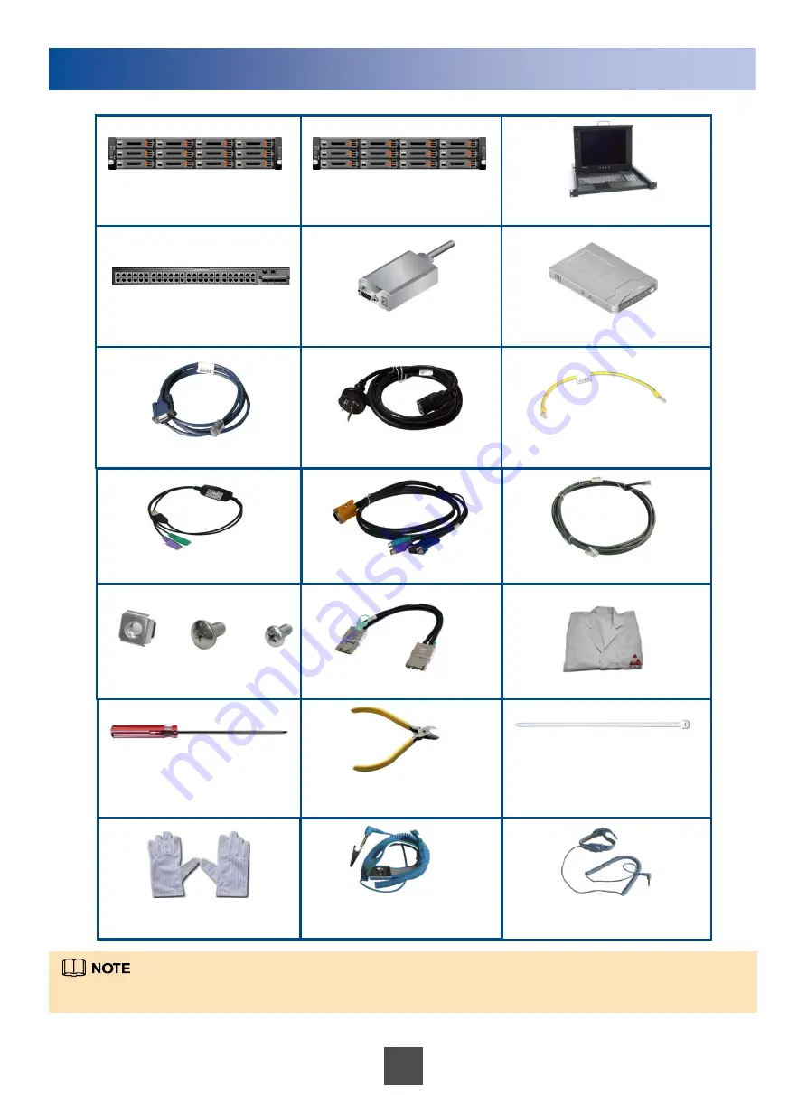
List of Tools and Materials 

PS/2 to USB converter 

KVM cables   

100M/1000M network cable 

Stack cables  

SD-Node 

C-Node 

KVM 

Switch 

SMS modem 

Remote modem 

AC power cable  


 ESD wrist strap with a crocodile clip 

Floating nut, M6 screw, and  
M4 screw 

ESD suite 

ESD wrist strap with a plug 

ESD gloves 

Phillips screwdriver 

Diagonal pliers 

1E1 trunk cable 

PGND cable 

Tie 

The previous table lists part of the materials required for installation. For the complete list, refer to the  

Packing List

.  

Summary of Contents for V100R001C01

Page 1: ...ng data on the hard disks first and then send a shutdown command through the operating system OS Copyright Huawei Technologies Co Ltd 2012 All rights reserved Installation Process The power distribution system DC or AC power distribution box auxiliary tools guide rails and floating nuts are pre installed and cables includingpower cables and network cables are laid out in the system cabinet of the ...

Page 2: ...Remote modem AC power cable ESD wrist strap with a crocodile clip Floating nut M6 screw and M4 screw ESD suite ESD wrist strap with a plug ESD gloves Phillips screwdriver Diagonal pliers 1E1 trunk cable PGND cable Tie The previous table lists part of the materials required for installation For the complete list refer to the Packing List ...

Page 3: ...rap with a plug insert the plug into the ESD jack on the cabinet scenario 1 For an ESD wrist strap with a crocodile clip snap the clip onto the cabinet scenario 2 Scenario 1 Wearing an ESD wrist strap with a plug Scenario 2 Wearing an ESD wrist strap with a crocodile clip 1 Wearing an ESD Suite 3 ...

Page 4: ...f the number of C Nodes exceeds three or the number of OSN nodes exceeds three an expansion cabinet is required If an expansion cabinet is used install the back end storage devices in the storage space of 1 U to 22 U and C Nodes in the positions of 32 U to 41 U Devices in the expansion cabinets must be parallel to the devices of the same type in the system cabinet The CSE uses a cloud storage syst...

Page 5: ...talling a KVM 2 1 Install the KVM balancing pole to the rear of the cabinet 3 Slide the KVM along the guide rails 5 Installing a Switch 2 3 1 Fix the mounting ears on each side of the switch by using M4 panel screws Slide the switch along the guide rails Fix the mounting ears on the square hole bar of the cabinet by using M6 panel screws Fix the mounting ears on the square hole bars of the cabinet...

Page 6: ...he same as that of an SD Node Install the C Nodes by referring to the installation procedure of an SD Node A C Node weighs 29 kg in its full configuration so at least two persons are required to mount the C Node into the cabinet After the previous devices have been installed you are advised to install filler panels to cover empty positions to ensure good ventilation If an SMS modem or a remote mod...

Page 7: ...that you can connect cables of the SD Node conveniently The remote modem is connected to an external power supply instead of the cabinet power supply Ensure that the remote modem does not affect the cabling of other devices or opening closing of the cabinet door Because the SD Node provides only one serial port you cannot connect an SMS modem and a remote modem at the same time 9 Installing a Remo...

Page 8: ...onnections Connect the network cables by referring to the labels Before connecting the network cables make sure that the devices have been grounded securely This figure shows the network cable connections among devices of the CSE Power cable connections and ground cable connections are not illustrated ...

Page 9: ...de 1 Slot0 B 25 26 SD Node 2 Slot 0 B C Node 1 Slot2 B 27 28 C Node 2 Slot 2 B C Node 3 Slot2 B 29 30 31 32 33 34 SD Node 1 Slot0 A 35 36 SD Node 2 Slot 0 A C Node 1 Slot2 A 37 38 C Node 2 Slot 2 A C Node 3 Slot2 A 39 40 41 42 43 44 45 46 47 48 b Distribution of network ports on switch 2 Device Port Switch port Number Switch port Number Device Port 1 2 3 4 5 6 7 8 MDS1 Slot0 A 9 10 MDS1 Slot3 A MD...

Page 10: ... 2 as an example to describe cable connections of an SD Node Connect cables of SD Node 1 in the same way The SMS modem connects only to SD Node 2 Connect cables in the sequence of the ground cables network cables then power cables This section uses C Node 1 as an example to describe cable connections of a C Node Connect cables of other C Nodes in the same way ...

Page 11: ... delivered with the KVM 9 Connecting the Remote Modem 6 Connecting the LAN Switch Rear panels of the two switches in a cabinet are connected to each other through two crossed stack cables If the CSE has an expansion cabinet switches in the system cabinet are connected to those in the expansion cabinet through four network cables ...

Page 12: ...g it to an external power supply Power on the other devices by pressing their power buttons Mandatory Optional Connect the cabinet to the external power Power on the LAN Switch Power on the modem Power on the KVM Power on the back end storage devices Power on the SD Node Power on the C Node 1 Device Power On Sequence No Name Normal State 1 System power indicator Steady green 2 Disk online indicato...

Page 13: ...the expansion network adapter Steady green The data transfer rate between the SD Node and application server AS is 100 Mbit s 6 Link indicator of the management network port Steady green 7 8 LINK indicator of the service network port on the onboard network adapter Steady green The data transfer rate between the SD Node and application server AS is 1000 Mbit s ...

Page 14: ...SE management environment End Configure the C node Configure the SD node Configure switches Preconfiguration Configure nodes Start deployment Verify the deployment result Start the ISM service Configure event notification Mandatory parent item Mandatory child item Set the client browser Optional child item Install the management system of the CSE Log in to the ISM service Configure the system Inst...

Reviews: