1
Installing a BBU Subrack
a
Installing a BBU
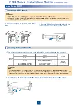
1. The following figure shows the slots in the subrack for installing boards and modules.
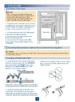
1. Install cable claws on the two sides of the
BBU.
2. Side the BBU along the guide rails into the
cabinet and secure screws on the panel.
Installing Boards and Modules
b
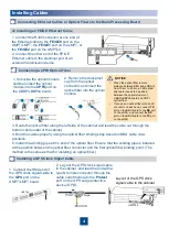
2. Insert the boards and modules into the correct slots and secure screws on the panel.
• Wear ESD wrist strap or ESD gloves to prevent electrostatic damage to the subrack.
• Only when the BBU install in TP48200A and APM30H cabinets, subrack cable claws are configured. Other
cabinets carry on next step directly.
NOTE
The figure shows only installation slots for the main processing board, core network processing board,
baseband processing board, fan module, and power module in the typical configuration. If you need to install
the USCUb22, UEIU, or UFLP, see
“Installing Boards and Modules” in
eNodeB Product Documentation.
NOTE
BBU Quick Installation Guide
V100R005C10 03
Slot0
Slot1
Slot2
Slot3(UBBP/LBBPd4)
Slot7(UMPT/LMPT)
Slot4
Slot5
Slot6(CNPUb/CNPU)
Slot16
(FANe)
Slot18
Slot19
(UPEUd)

